
Magneto-rheological torsion damper

A torsional vibration damper and magnetorheological technology, applied in non-rotation vibration suppression, vibration suppression adjustment and other directions, can solve the problems of complex processing and limited damping force, and achieve improved adjustable damping force, large damping force, and extended design. Effects of theory and scope of application

Active Publication Date: 2013-04-03
SUZHOU SHIHAO BUILDING MATERIAL NEW TECH ENG
View PDF6 Cites 42 Cited by
  • Summary
  • Abstract
  • Description
  • Claims
  • Application Information

AI Technical Summary

Problems solved by technology

Chinese patent (CN201110115093.9) improves the traditional silicone oil shock absorber, and proposes a magnetorheological torsional shock absorber for engines, which can change the applied magnetic field force by changing the magnitude of the current, thereby adjusting the magnetorheological fluid damping, since only the shear mode of operation is utilized, the resulting damping force is limited
Chinese patent (CN20092026277.9) proposes a magnetorheological torsional vibration damping device. When the rotor rotates, the magnetorheological fluid flows radially due to the angle with the horizontal direction, and then reciprocates along the channel in the stator. , also has certain limitations, the processing is complicated, and the torsional vibration damping itself is prone to generate new torsional vibrations

Method used


Image

  • Magneto-rheological torsion damper
  • Magneto-rheological torsion damper

Examples


Embodiment Construction

[0024] The present invention will be further elaborated below in conjunction with accompanying drawing:

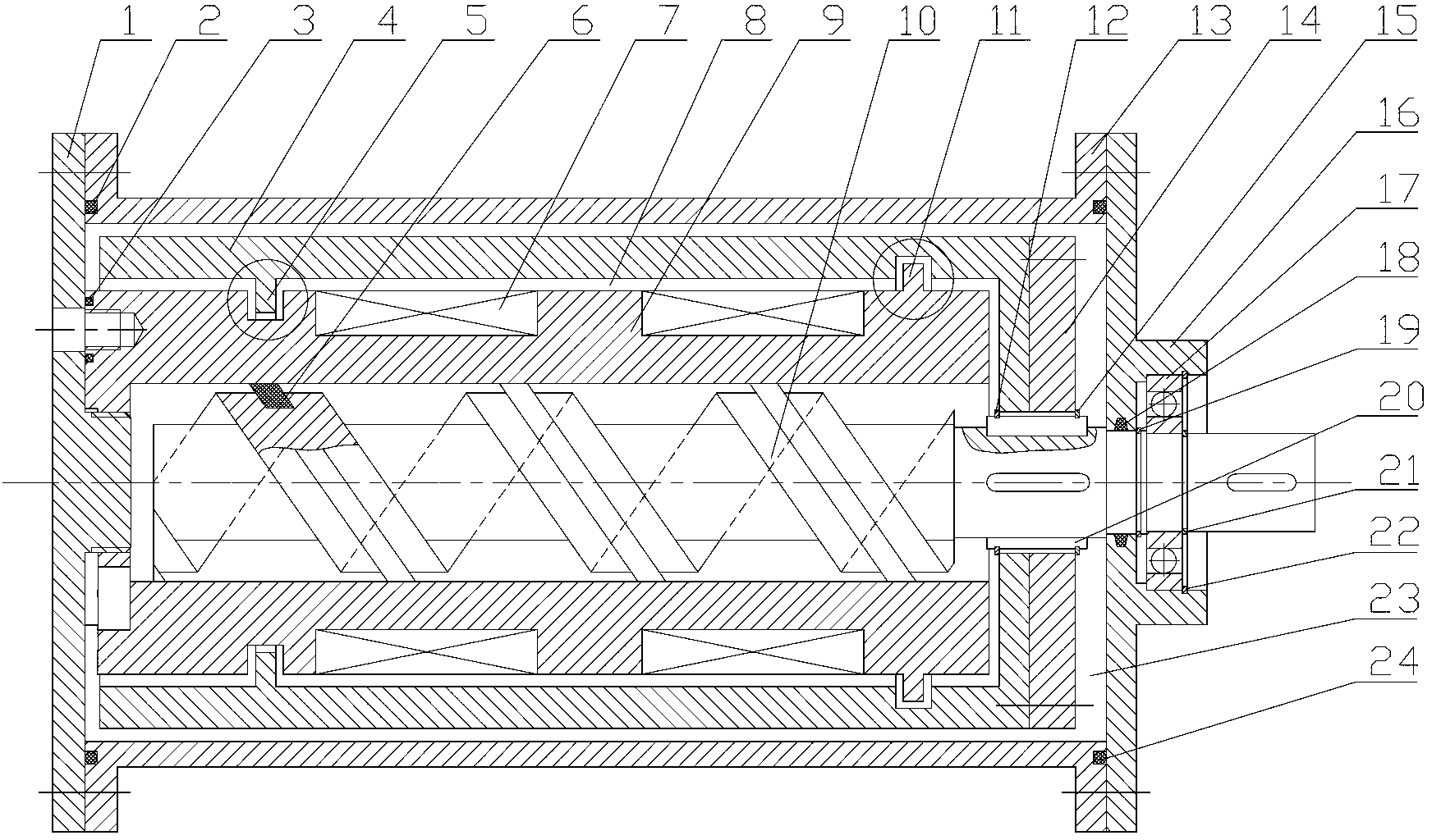
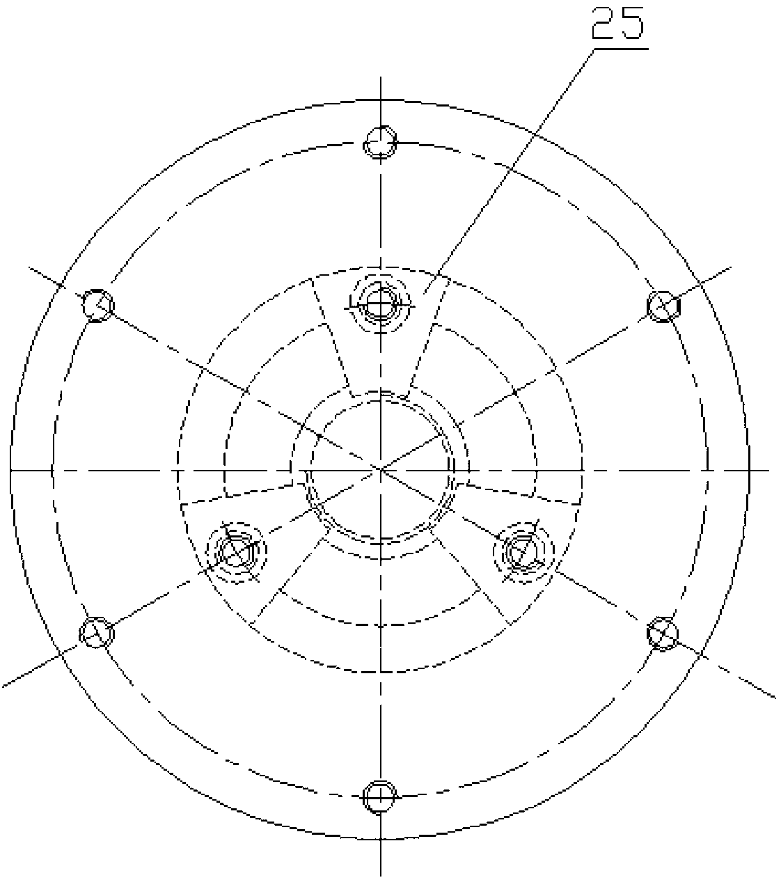
[0025] see figure 1 and figure 2 , The magnetorheological torsional shock absorber proposed by the present invention includes a rotor assembly, a stator 9 wound with an electromagnetic coil, a magnetorheological fluid 23, a sealed bearing 17 and a shock absorber cylinder. The rotor assembly is composed of a propulsion rod 10 with a helical propulsion structure, an inner sleeve 4 fixedly connected with the propulsion rod and a connecting disc 14, and the input end of the rotor assembly is connected with the load equipment through a coupling. The shock absorber cylinder is formed by connecting the outer sleeve 13 and the left and right end covers 1 and 16.

[0026] The stator 9 is firmly connected with the shock absorber cylinder, and the outer circle is wound with multi-level electromagnetic coils 7 . A propulsion rod 10 with a helical propulsion structure performs rota...


PUM


Abstract

The invention relates to a magneto-rheological torsion damper, which mainly comprises a stator, a rotor, a spiral propulsion rod and a shock absorber cylinder body, wherein the input end of the magneto-rheological torsion damper is connected with loading equipment via a coupler; the stator is wound with multiple stages of electromagnetic coils; a groove or a bulge matched with the rotor is processed on the outer wall of the stator; a certain gap is formed between the outer wall of the stator and an inner sleeve; a bulge or groove matched with the stator is processed on the inner wall of a rotor cylinder; the propulsion rod with a spiral propulsion structure, the rotor and the spiral propulsion rod are mutually connected via a terminal pad; the shock absorber cylinder body consists of an outer sleeve, a sealing bearing, a left cover plate and a right cover plate; a certain gap is formed between the shock absorber cylinder body and the inner sleeve; and the gap between the stator and the shock absorber cylinder body as well as the gap between the shock absorber cylinder body and the rotor is full of magneto-rheological fluid. According to the magneto-rheological torsion damper disclosed by the invention, two working modes of magneto-rheological fluid shearing and flowing are fully utilized, and the magneto-rheological torsion damper has the advantages of compact structure, big adjustable damping force and wide dynamic range and can be widely applied to the occasion of torsional vibration control.

Description

technical field [0001] The invention belongs to shock absorbers, in particular to a magneto-rheological torsion absorber. Background technique [0002] Engine crankshafts, machine tool spindles, motors and other transmission shafts or rotors that perform rotary motion will inevitably undergo torsional vibration during work. This vibration will not only reduce the accuracy of the machine, increase noise and other faults, and even cause crankshaft or transmission shaft. Damage due to fatigue failure, especially at high speeds. In addition, for high-power lifting equipment such as elevators and construction elevators that do linear motion, a large amount of energy is consumed during the descent of goods, and a large resistance is required to reduce the damage to goods during an emergency fall. Therefore, the design of the torsional vibration damper has become an important subject to improve the above situation. [0003] At present, the torsional shock absorbers used at home a...

Claims


Application Information

Patent Timeline
IPC IPC(8): F16F9/53
Inventor 董小闵王小龙古晓科丁飞耀
Owner SUZHOU SHIHAO BUILDING MATERIAL NEW TECH ENG
Learn More