Waste heat recovery heating system of biomass power plant

A waste heat recovery and heating system technology, which is applied in the circulation cooling water of biomass power plants, slag waste heat recovery heating system, and flue gas fields, can solve the problems of difficult recovery and utilization of waste heat, and achieve the effect of high heat recovery and utilization rate

Inactive Publication Date: 2013-04-03
ZHEJIANG GONGSHANG UNIVERSITY
View PDF7 Cites 10 Cited by
  • Summary
  • Abstract
  • Description
  • Claims
  • Application Information

AI Technical Summary

Problems solved by technology

[0003] Aiming at the problem that waste heat such as circulating cooling water, flue gas, and slag is difficult to recover and utilize in the prior art, the present invention provides a heat supply system that adopts heat pump technology, flue gas heat exchanger, and slag heat exchanger to recover waste heat from a biomass power plant system

Method used


Image

  • Waste heat recovery heating system of biomass power plant

Examples


Embodiment Construction

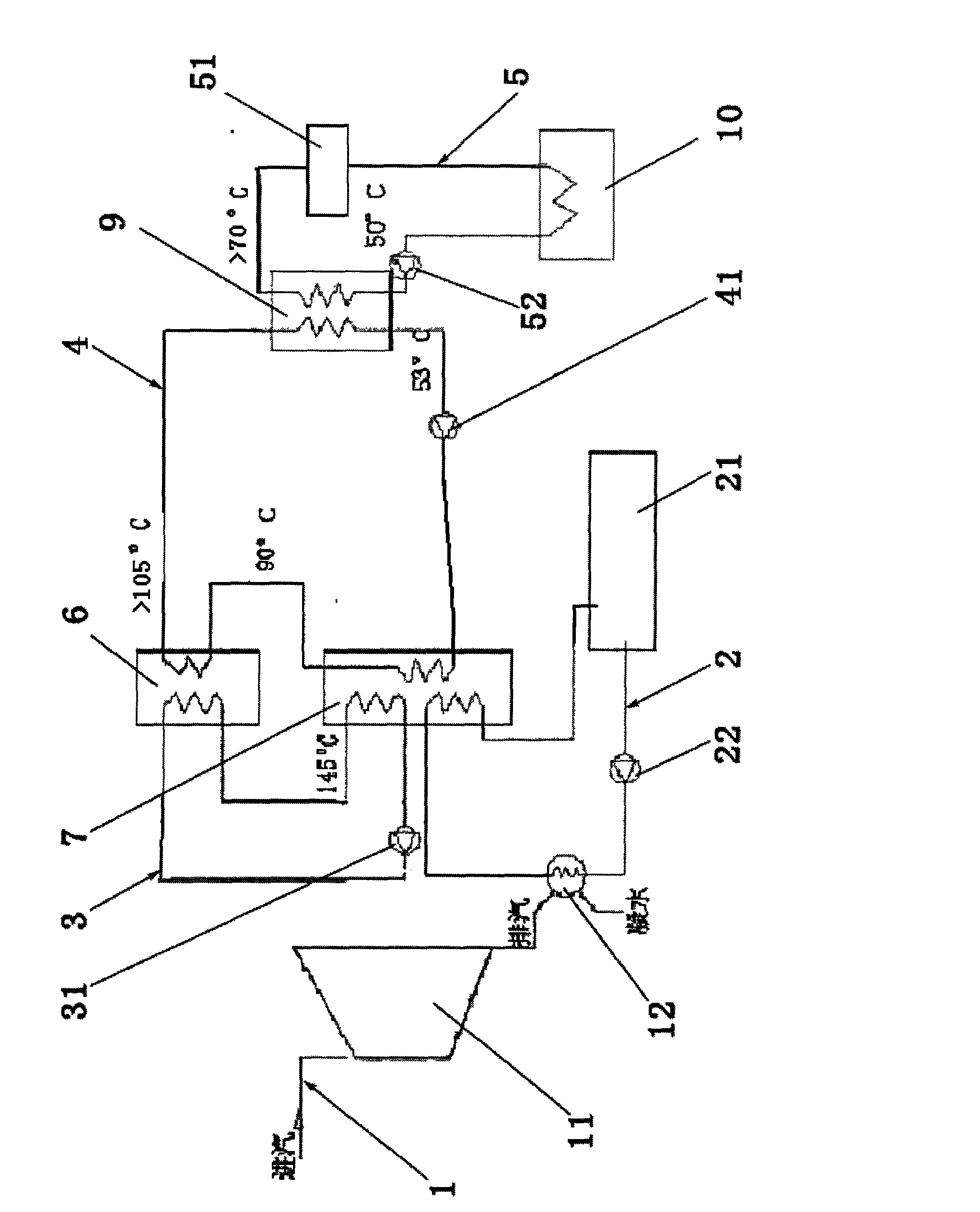
[0016] Attached below figure 1 The present invention is described in further detail with the specific embodiment:

[0017] A biomass power plant waste heat recovery heating system, such as figure 1 As shown, it includes a steam pipeline 1 , a circulating cooling water pipeline 2 , a flue gas heat exchange pipeline 3 , an internal circulation pipeline 4 and a heat supply pipeline 5 .

[0018] The steam pipeline 1 is connected to the steam turbine 11 and the condenser 12; the circulating cooling water pipeline 2 starts from the cooling circulating water pool 21 and returns to the cooling circulating water pool 21 after passing through the circulating cooling water pump, the condenser 12 and the absorption heat pump 7. After the steam in the steam pipeline 1 passes through the steam turbine 11 to do work, the exhaust steam discharged from the turbine 11 is transported to the condenser 12, and the exhaust steam passes through the condenser 12 to transfer heat energy to the coolin...


PUM


Abstract

The invention relates to a heat recovery device, and discloses a waste heat recovery heating system of a biomass power plant. The waste heat recovery heating system comprises a steam line, a cooling water circulation line, an inner circulation line and a heating line, wherein the heating line is connected with a slag heat exchanger, and is connected to a heat user side after heat is absorbed by a water heat exchanger. The waste heat recovery heating system recovers waste heat in flue gas, slag and circulating cooling water of the biomass power plant in a heat exchange mode to be used for life and production heat supply, and the waste heat recovery heating system has the advantages of high recovery use ratio of heat energy, energy conservation, environmental protection and the like.

Description

technical field [0001] The invention relates to a waste heat recovery device, in particular to a biomass power plant circulation cooling water, flue gas and slag waste heat recovery heating system. Background technique [0002] The heat energy of the circulating cooling water of the biomass power plant passes through the cooling tower, the heat of the flue gas is discharged into the atmosphere through the chimney, resulting in huge heat loss, and the heat energy of the slag is discharged into the environment through the ash, which is the main reason for the low efficiency of energy use in the biomass power plant. Cause the waste of energy and water or electricity, also pollute environment and atmosphere seriously simultaneously. An important difference between biomass power plants and coal-fired thermal power plants is that the sulfur content in the combustion waste gas of biomass power plants is extremely low, and sulfuric acid will not be formed after condensation, which w...

Claims


Application Information

Patent Timeline
Patent Type & Authority Applications(China)
IPC IPC(8): F24D3/18
CPCY02B30/12
Inventor 李同强
Owner ZHEJIANG GONGSHANG UNIVERSITY
Why Eureka
Try Eureka