Polarization maintaining optical fiber with small bending radius and manufacture method of polarization maintaining optical fiber
A polarization-maintaining optical fiber and bending radius technology, applied in polarized optical fiber, cladding optical fiber, manufacturing tools, etc., can solve the problems of the development of optical fiber sensor devices in the direction of miniaturization, the difficulty of making optical fiber sensor devices of large size, and the inability to meet people's needs, etc. , to achieve the effect of improving crosstalk stability, reducing stress interference, and improving bending resistance
- Summary
- Abstract
- Description
- Claims
- Application Information
AI Technical Summary
Problems solved by technology
Method used
Image

Examples
Embodiment 1
[0050] Embodiment 1: The radius of the quartz cladding 1 is 40um.
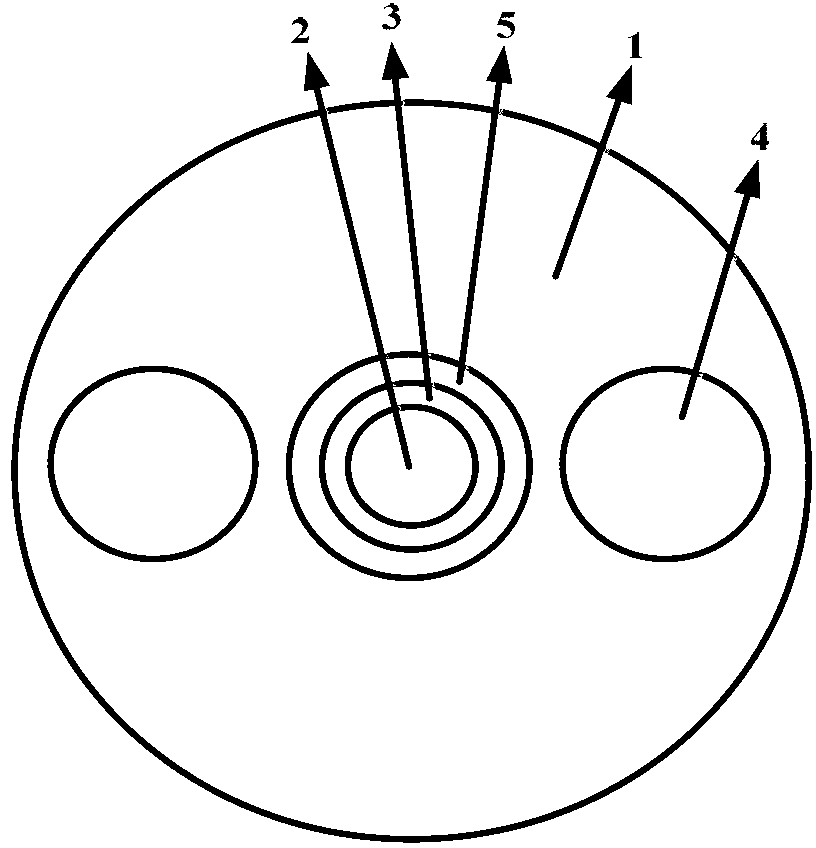
[0051] The core rod is made by plasma chemical vapor deposition method combined with the sleeve method. The core rod includes a core layer 2, a second quartz cladding ring 3 and a third quartz cladding ring 5; a sleeve is placed on the outside of the core rod to form a solid rod 6. The casing forms a quartz cladding 1 . Two stress through holes are axially opened on the solid rod 6, and the stress through holes are arranged symmetrically along the center of the core layer 2. When opening the stress through holes, diamond drills are used, combined with mechanical positioning, infrared induction positioning and electronic control.
[0052] Two boron-doped stress rods 7 are made by doping silicon dioxide with boron by plasma method, and the stress rod 7 made by plasma method has better uniformity. The surface of the stress rod 7 is treated so that the outer diameter of the stress rod 7 is 0.1 mm smaller than the...
Embodiment 2
[0060] Embodiment 2: The radius of the quartz cladding 1 is 62.5um.
[0061] Plasma chemical vapor deposition method combined with sleeve method is used to manufacture core rod, core rod includes core layer 2, second quartz cladding ring 3 and third quartz cladding ring 5; , the casing forms a quartz cladding 1 . Two stress through holes are axially opened on the solid rod 6, and the stress through holes are arranged symmetrically along the center of the core layer 2. When opening the stress through holes, diamond drills are used, combined with mechanical positioning, infrared induction positioning and electronic control.
[0062] Two boron-doped stress rods 7 are made by doping silicon dioxide with boron by plasma method, and the stress rod 7 made by plasma method has better uniformity. The surface of the stress rods 7 is treated so that the outer diameter of the stress rods 7 is 0.2 mm smaller than the diameter of the stress through hole, and each stress rod 7 is combined wit...
Embodiment 3
[0071] Embodiment 3: The radius of the quartz cladding 1 is 20um.
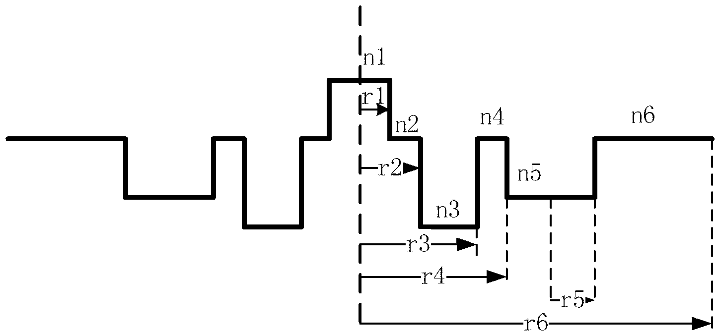
[0072] The present invention also carries out the research and development of the extremely small polarization-maintaining optical fiber whose cladding radius 1 is 20um. The radius of the core layer 2 is 3.0um, and the relative refractive index difference between the core layer 2 and the quartz cladding layer 1 is 0.6%. The radius of the second quartz cladding ring 3 is 3.3um, and the radius ratio of the second quartz cladding ring 3 to the core layer 2 is 1.1. The radius of the third quartz cladding ring 5 is 4.5um, the radius ratio between the third quartz cladding ring 5 and the core layer 2 is 1.5, and the relative refractive index difference between the third quartz cladding ring 5 and the quartz cladding 1 is -0.5 %. Half of the shortest distance between two stress cat's eyes 4 is 6.0um, and the ratio of half of the shortest distance between two stress cat's eyes 4 to the radius of the core layer 2 is ...
PUM
| Property | Measurement | Unit |
|---|---|---|
| radius | aaaaa | aaaaa |
| additional attenuation | aaaaa | aaaaa |
| additional attenuation | aaaaa | aaaaa |
Abstract
Description
Claims
Application Information
 - R&D
- Intellectual Property
- Life Sciences
- Materials
- Tech Scout
- Unparalleled Data Quality
- Higher Quality Content
- 60% Fewer Hallucinations
Browse by: Latest US Patents, China's latest patents, Technical Efficacy Thesaurus, Application Domain, Technology Topic, Popular Technical Reports.
© 2025 PatSnap. All rights reserved.Legal|Privacy policy|Modern Slavery Act Transparency Statement|Sitemap|About US| Contact US: help@patsnap.com