Residual oil hydrotreating method

A treatment method, the technology of residual oil hydrogenation, which is applied in the field of residual oil hydrogenation, can solve the problems of unreachable reaction temperature, lowering, and inability to realize operation, and achieve the effects of improving effective utilization rate, stable product properties, and extending operation cycle

Active Publication Date: 2013-04-24
CHINA PETROLEUM & CHEM CORP +1
View PDF6 Cites 41 Cited by
  • Summary
  • Abstract
  • Description
  • Claims
  • Application Information

AI Technical Summary

Problems solved by technology

The problem with this technology is that, according to the technical key disclosed in this patent, when the pressure drop of at least one bed in the first hydrogenation reaction zone reaches the upper limit or after a hot spot appears in the zone, the pressure drop to the second hydrogenation reaction zone The amount of residual oil directly introduced is bound to be lower than the original feed amount, which is equivalent to the reduction operation
By reducing feedstock oil, especially residual oil feed, the utilization rate of the catalyst is improved and the operation period of the unit is extended. However, in the catalyst loading method in this technology, since the protective agent and demetallization catalyst are loaded in the

Method used


Image

  • Residual oil hydrotreating method
  • Residual oil hydrotreating method

Examples


Embodiment 1

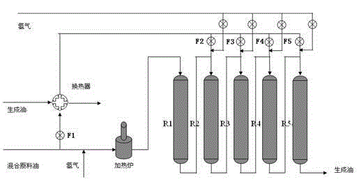
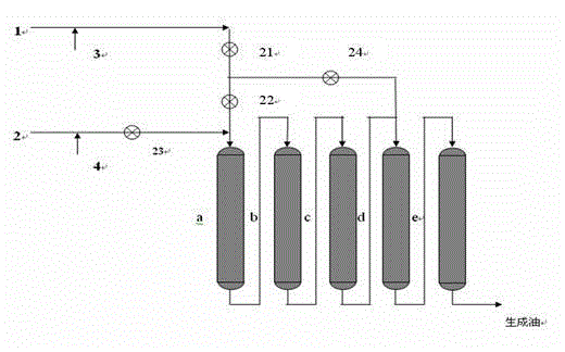
[0039] Such as figure 1 As shown, according to the residual oil hydroprocessing method provided by the present invention, a fixed-bed hydroprocessing experimental device has been designed by itself. Each reactor of the device has an effective volume of 3L. Such 5 reactors are used in series, and the feedstock oil is from top to bottom. The following process flow. Wherein the second, third, fourth and fifth reactor upper inlets are additionally equipped with quenching feed pipelines for the split part of raw material oil. In this test, FZC series residue hydrotreating catalysts developed by Fushun Petrochemical Research Institute were used, including hydrogenation protection agent (FZC-1 series), hydrodemetallization catalyst (FZC-2 series), hydrodesulfurization catalyst (FZC -3 series) and hydrodenitrogenation and carbon removal catalysts (FZC-4 series).

[0040] The catalyst loading results of each reactor are:

[0041] The catalysts loaded from top to bottom in R1 reactor...

Embodiment 2

[0051] Such as figure 1 The shown fixed-bed hydrotreating experimental device, the process flow remains the same as in Example 1.

[0052] The loading results of catalysts in R1, R2, R3, R4 and R5 reactors are shown in Table 4.

[0053] Table 4 Catalyst loading ratio of each reactor

[0054] reactor R1 R2 R3 R4 R5 FZC-11A, v% 2 2 - - - FZC-12A, v% 10 10 5 2 - FZC-13A, v% 1.5 1.5 1.5 1.5 - FZC-28AM (thick strip), v% 1.5 1.5 1.5 1.5 - FZC-28A, v% 30 15 10 - - FZC-28, v% 55 20 20 10 - FZC-204, v% - 30 30 35 - FZC-33, v% - 20 12 20 10 FZC-34, v% - - 20 30 10 FZC-41A, v% - 80 Total, v% 100 100 100 100 100

[0055] After the catalyst is filled and the device is airtight and qualified, vulcanization and feed oil switching are carried out. After the reaction activity of the catalyst is stable, at a reaction pressure of 16 MPa, an average reaction temp...


PUM


Abstract

The invention discloses a residual oil hydrotreating method. According to the method, under hydrotreating conditions, a residual oil raw material and hydrogen pass through at least 4 reactors connected in series in order, all the reactors except the last one are provided with a protective agent and a demetallization catalyst, and along the material flowing direction, the ratios of the protective agent and the demetallization catalyst decrease gradually in the downstream reactors. After the equipment operates for 700-4000h, shunt operation is carried out. The feeding amount of a first reactor is reduced or maintained constant. The feeding amount of each reactor between the first reactor and the last reactor is increased, and the increased residual oil raw material is injected at the inlets of the middle reactors. Compared with the prior art, the method provided in the invention can obviously prolong the operation period of residual hydrogenation equipment, and make the effective utilization rate of the catalyst and the equipment running time achieve consistency, thereby enhancing the equipment running efficiency and improving the economical efficiency.

Description

technical field [0001] The invention relates to a residual oil hydrogenation method, which is suitable for the hydrogenation treatment process of heavy residual oil, especially the hydrogenation treatment process of fixed bed heavy residual oil. Background technique [0002] As crude oil becomes heavier and inferior, and environmental protection regulations become increasingly stringent, fixed-bed hydroprocessing technology is the main method for upgrading residue oil. It is widely used and has mature technology. It can be combined with heavy oil catalytic cracking unit to make residue oil lighter. Prolific transportation fuel oil. Heavy raw oil contains a large amount of sulfur, nitrogen, oxygen, nickel, vanadium and other heteroatoms, unsaturated hydrocarbons, macromolecular colloids and asphaltenes. The reaction process of residual oil hydrotreating is complex and changeable, the raw material structure is complex, and the molecular weight distribution is broad. To compl...

Claims


Application Information

Patent Timeline
IPC IPC(8): C10G65/04
Inventor 王志武王刚王欣安晟杨刚隋宝宽吴国林
Owner CHINA PETROLEUM & CHEM CORP
Why Eureka
Try Eureka