Airglow-discharge low-temperature plasma coating technique
A technology of low-temperature plasma and atmospheric glow, which is applied in the direction of fusion spraying, metal material coating process, coating, etc., can solve the problems of complex, damaged substrate preparation process, and low coating temperature, so as to expand the scope of use and reduce the The complexity of the preparation process and the good coating effect
- Summary
- Abstract
- Description
- Claims
- Application Information
AI Technical Summary
Problems solved by technology
Method used
Image

Examples
Embodiment 1
[0027] In this embodiment, the selected gas is N 2 ; The excitation source is a DC pulse power supply; the electrode material is made of graphite electrodes, and the discharge tube is made of polytetrafluoroethylene. The coating process is as follows:
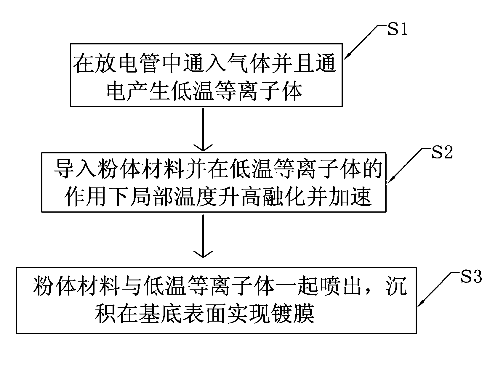
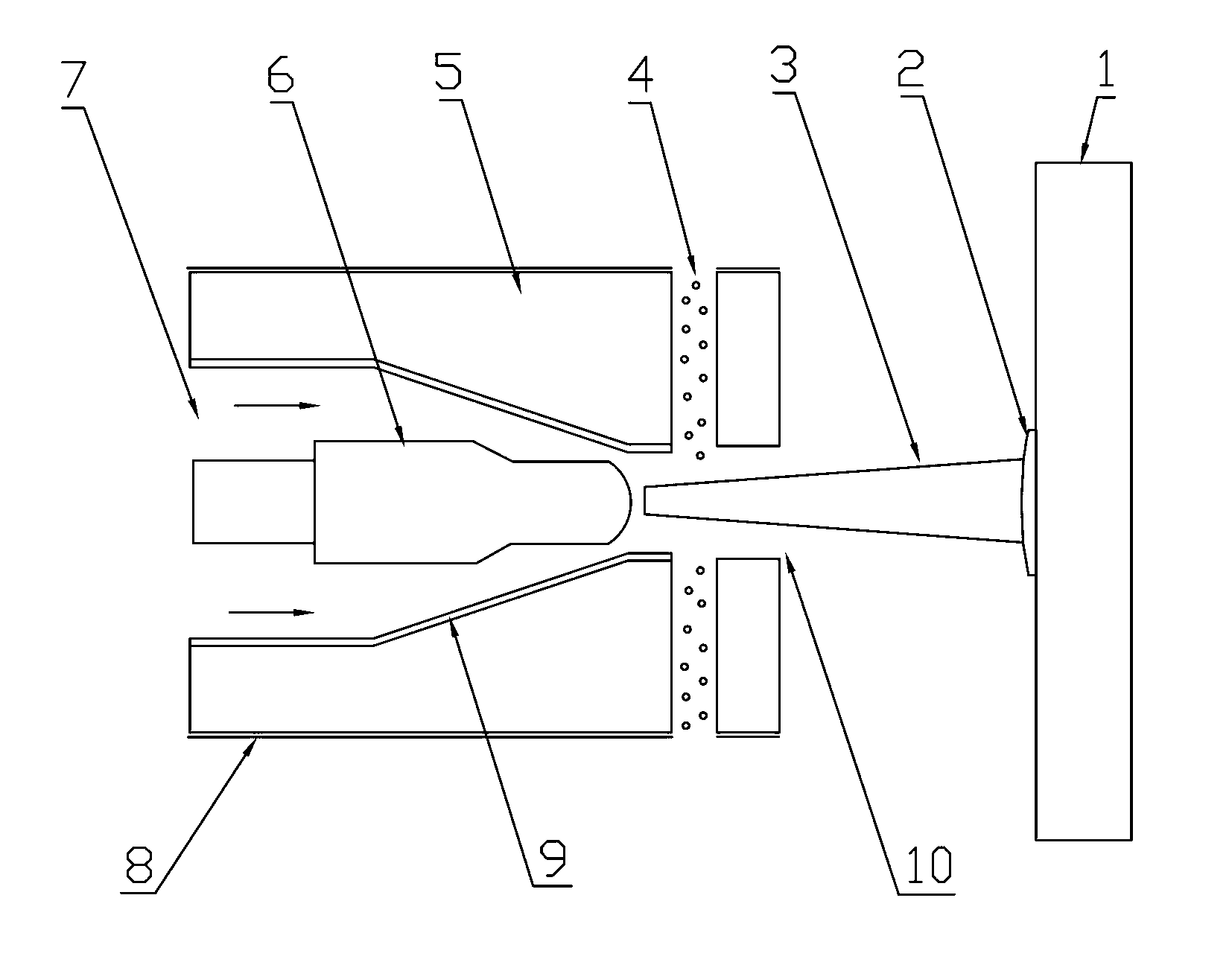
[0028] S1, the N 2 The gas inlet 7 leads to the discharge tube 1, and the gas flow rate is 6-20L / min; a DC pulse power supply is added to the anode 5 and cathode 6, the voltage range is 2-15KV, the pulse frequency range is 7KHz-50KHz, and the pulse voltage width 600nm-80μm; the temperature of the generated low-temperature plasma 3 is 10-100°C. S2, the powder feeding rate of the powder material introduced through the powder inlet 4 is 10-25g / min, and the local temperature rises under the action of the low-temperature plasma 3; S3, the powder material melts and accelerates out of the nozzle 10, depositing The thin film 2 is deposited on the surface of the substrate 1; the distance between the nozzle 10 and the substrate 1 is 1...
Embodiment 2
[0030] In this embodiment, the gas is Ar; the excitation source is a radio frequency power supply; the electrode material is a tungsten electrode, and the discharge tube is made of alumina. The coating process is as follows:
[0031] S1, Ar is passed into the discharge tube 1 from the gas inlet 7, and the gas flow rate is 10-20L / min; add a radio frequency power supply to the anode 5 and the cathode 6, the power supply power is 10-300mW, and the pulse frequency range is 7.17MHz-15MHz, The preferred frequency is 13.56MHz; the temperature of the generated low-temperature plasma 3 is 50-150°C. S2. The powder feeding rate of the powder material introduced through the powder inlet 4 is 10-35g / min, and the local temperature rises under the action of the low-temperature plasma 3 . S3. The powder material is melted and accelerated out of the nozzle 10, and deposited on the surface of the substrate 1 to form a thin film 2; the distance between the nozzle 10 and the substrate 1 is 100mm...
Embodiment 3
[0033] In this embodiment, the selected gas is N 2 Mixed gas with Ar; the excitation source adopts AC power; the electrode material adopts copper electrode, and the discharge tube is made of boron nitride material. The coating process is as follows:
[0034] S1, the N 2 Pass the gas inlet 7 into the discharge tube 1, and the gas flow rate is 6-20L / min; Ar is passed into the discharge tube 1 through the gas inlet 7, and the gas flow rate is 1-10L / min; AC power supply, the voltage range is 5-50KV, the pulse frequency range is 20KHz-50KHz; the temperature of the generated low-temperature plasma 3 is 70-100°C. S2. The powder feeding rate of the powder material introduced through the powder inlet 4 is 10-35g / min, and the local temperature rises under the action of the low-temperature plasma 3 . S3. The powder material is melted and accelerated out of the nozzle 10, and deposited on the surface of the substrate 1 to form a thin film 2; the distance between the nozzle 10 and the s...
PUM
 Abstract
Description
Claims
Application Information
 - R&D
- Intellectual Property
- Life Sciences
- Materials
- Tech Scout
- Unparalleled Data Quality
- Higher Quality Content
- 60% Fewer Hallucinations
Browse by: Latest US Patents, China's latest patents, Technical Efficacy Thesaurus, Application Domain, Technology Topic, Popular Technical Reports.
© 2025 PatSnap. All rights reserved.Legal|Privacy policy|Modern Slavery Act Transparency Statement|Sitemap|About US| Contact US: help@patsnap.com