Gluing composite connection joint and gluing composite connection method for FRP (fiber reinforced polymer) section and barbed plates

A composite connection and barbed plate technology, applied in the processing of building materials, bridge parts, erection/assembly of bridges, etc., can solve the problems of low joint efficiency, large lap length, shear failure of profiles, etc., to improve the shear strength. , The effect of high joint efficiency and simple construction

Active Publication Date: 2015-07-08
SOUTHEAST UNIV +1
View PDF5 Cites 0 Cited by
  • Summary
  • Abstract
  • Description
  • Claims
  • Application Information

AI Technical Summary

Problems solved by technology

However, the profiles used in the field of civil engineering and transportation are mainly pultruded profiles, and the fiber direction of the pultruded profiles is mainly along the length direction of the profile. The joint efficiency of this type of profile bolt connection is lower than 30%, and the profile is often sheared off after the profile is squeezed by the bolt. destroy
On the other hand, due to the thicker FRP profiles in the field of civil engineering and transportation, if the cemented connection method is used, in order to ensure sufficient joint efficiency, the required lap length is relatively large, and in more cases it cannot be realized due to structural problems. lap length
Since the common stress of the two connection methods cannot be realized, the joint efficiency of cemented and mechanical hybrid joints cannot be effectively improved
[0004] To sum up, the current joint connection of FRP profiles in the field of civil engineering and transportation has the disadvantages of low joint efficiency and unguaranteed quality, which is far from meeting the needs of the project. This has also become a bottleneck for the application of FRP profiles in the field of civil engineering and transportation.

Method used


Image

  • Gluing composite connection joint and gluing composite connection method for FRP (fiber reinforced polymer) section and barbed plates
  • Gluing composite connection joint and gluing composite connection method for FRP (fiber reinforced polymer) section and barbed plates
  • Gluing composite connection joint and gluing composite connection method for FRP (fiber reinforced polymer) section and barbed plates

Examples


Embodiment 1

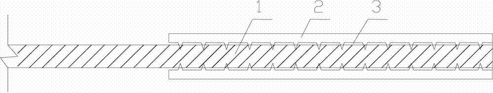
[0040] see figure 1 , figure 2 , image 3 , Figure 6 and Figure 7 Shown:

[0041]First, use a grinder to grind off the non-slip coating on the joint connection area of ​​the FRP profile 1. When grinding, care should be taken to control the grinding depth, preferably 0.5mm±0.1mm.

[0042] Secondly, calibrate the size of the joint on the FRP profile 1, and apply the epoxy resin impregnating glue 3 on the joint of the FRP profile 1, preferably with a thickness of 0.5mm±0.1mm.

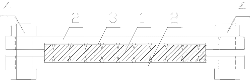
[0043] Thirdly, place one stabbing plate 2 on the plate surface of the static platform of the press, place the joint of the FRP profile 1 on the stabbing plate 2 and straighten it, place the other stabbing plate 2 on the FRP profile 1, and place the barbed plates of the two stabbing plates 2 The faces are all facing the FRP profile 1.

[0044] Fourth, start the press to pressurize, press the thorns of the thorn plate 2 into the FRP profile 1, and press the thorns into a certain depth: the thorn p...

Embodiment 2

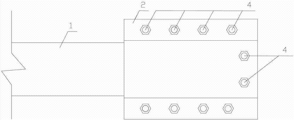
[0046] see figure 1 , Figure 4 and Figure 5 Shown:

[0047] Except for the following differences from Example 1, other parts are the same: there is no bolt hole for the upper and lower butt joints on the side of the spine plate 2, and there is no bolt hole at the end of the spine plate 2. The mounting bolt holes of the spine plate 2 are in the spine plate 2, so in When connecting with the FRP profile 1, bolt holes need to be opened at the corresponding positions of the FRP profile 1.

[0048] Compared with prior art methods, the beneficial effects of the present invention are:

[0049] 1. The connection between the thorn board and the FRP profile successfully introduces thorns into the shear interface of the glue layer, which greatly improves the shear strength of the glue layer interface, realizes the joint force of the cementation and the connection of the thorn board, and has high strength and good ductility , high joint efficiency and other advantages; please refer ...


PUM


Abstract

The invention discloses a gluing composite connection joint and a gluing composite connection method for an FRP (fiber reinforced polymer) section and barbed plates. The two barbed plates are respectively positioned on two surfaces of a joint connection area of the FRP section, barbed surfaces of the barbed plates face the FRP section, barbs of the two barbed plates are inserted into the FRP section, epoxy resin impregnation adhesive layers are arranged among the two barbed plates and the FRP section, and the two barbed plates are connected with each other by bolts. The gluing composite connection joint and the gluing composite connection method have the advantages that the barbs are successfully arranged in shear-resistant interfaces of the adhesive layers when the barbed plates are connected with the FRP section, the shear-resistant strength of the interfaces of the adhesive layers is greatly improved, effects of gluing and connection joint stress of the barbed plates are realized, the joint is high in strength and efficiency and good in ductility, and the like. Besides, the joint can be constructed simply, quickly, conveniently and reliably, the method can be used for one-way FRP section extension and multi-direction FRP connection, can also be used for processing external connection design for barbed plates, and is applicable to operation such as bolt connection and welding, and accordingly the joint can be applied to structures such as trusses made of composite materials, net racks and bridges.

Description

technical field [0001] The invention belongs to the technical field of civil engineering and transportation, and relates to an FRP profile splinter-bonded composite connection joint and a method thereof. Background technique [0002] FRP profiles for civil construction and transportation are made of epoxy resin as the matrix, untwisted fiber as the reinforcing material, and special additives are added at the same time. The profiles of different specifications are made by the pultrusion process. They have high specific strength and specific stiffness. Corrosion, good fatigue resistance and designability. [0003] In the field of civil engineering and transportation, the application of FRP profiles started relatively late. At present, the connection of FRP profiles in this field basically follows the joint connection methods of composite materials in the aerospace field: cemented connection, mechanical connection and a hybrid connection of the two. The profiles used in the a...

Claims


Application Information

Patent Timeline
Patent Type & Authority Patents(China)
IPC IPC(8): E04B1/38E04B1/58E04G21/00E01D19/00E01D21/00
Inventor 吴刚詹瑒张保龙蒋剑彪
Owner SOUTHEAST UNIV
Why Eureka
Try Eureka