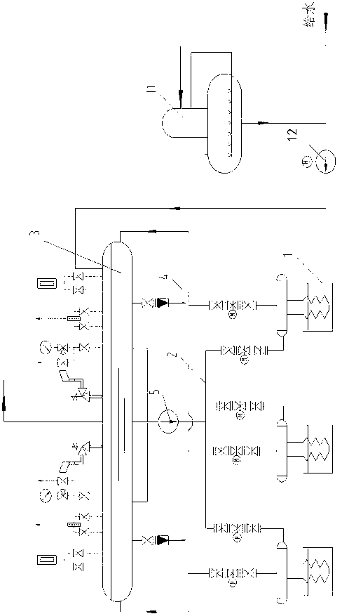
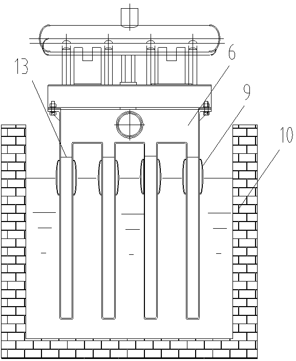
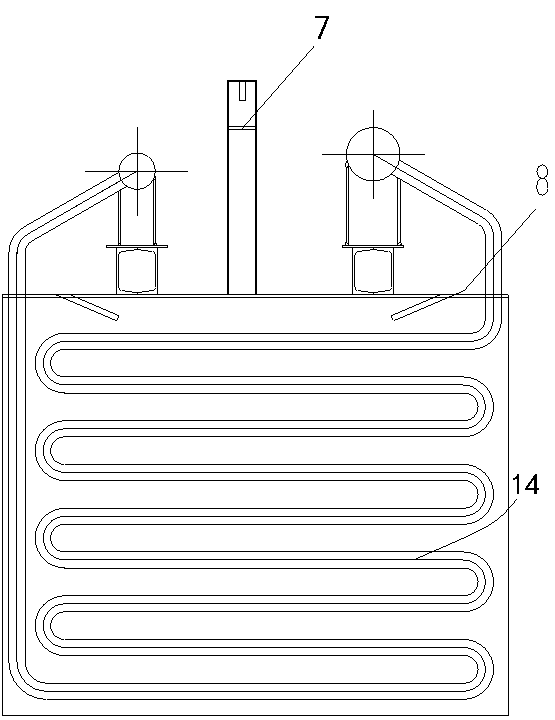
ISP (imperial smelting process) cooling chute waste heat boiler system

A waste heat boiler and cooling chute technology, used in steam boilers, furnaces, waste heat treatment and other directions, can solve the problems of high temperature of superheated steam parameters, complicated installation, and inability to achieve large-scale engineering applications, so as to reduce process energy consumption and improve The effect of energy saving levels

Inactive Publication Date: 2013-04-24
BEIJING CENTURY BENEFITS
View PDF2 Cites 0 Cited by
  • Summary
  • Abstract
  • Description
  • Claims
  • Application Information

AI Technical Summary

Problems solved by technology

The chute boiler is not widely used in lead-zinc enterprises for the following reasons: (1) The chute boiler is composed of a superheater and an evaporator, and the system is complex
The superheater uses steam to exchange heat, and the heat transfer coefficient is several orders of magnitude lower than that of the evaporator, which requires a larger heating surface. The original water-cooled cooling chute has insufficient space, so the cross-sectional area and volume of the chute need to be enlarged
If this method is used to recover waste heat, the main body of the cooling chute equipment needs to be modified; (2) Although the protective cover and combined financ

Method used


Image

  • ISP (imperial smelting process) cooling chute waste heat boiler system
  • ISP (imperial smelting process) cooling chute waste heat boiler system
  • ISP (imperial smelting process) cooling chute waste heat boiler system

Examples


Embodiment Construction

[0019] The present invention will now be described more fully with reference to the accompanying drawings, in which exemplary embodiments of the invention are shown. This invention may, however, be embodied in many different forms and should not be construed as limited to the exemplary embodiments set forth herein. Rather, these embodiments are provided so that this disclosure will be thorough and complete, and will fully convey the scope of the invention to those skilled in the art.

[0020] For ease of description, spatially relative terms such as "upper," "lower," "left," and "right" may be used herein to describe the relationship of one element or feature relative to another element or feature shown in the figures. It will be understood that the spatial terms are intended to encompass different orientations of the device in use or operation in addition to the orientation depicted in the figures. For example, if the device in the figures is turned over, elements described ...


PUM


Abstract

The invention discloses an ISP (imperial smelting process) cooling chute waste heat boiler system comprising a steam manifold and a plurality of parallelly arranged chute heat exchangers. Each chute heat exchanger comprises a lead and zinc chute, a comb-shaped heat exchange box and a heat exchange tube, lead and zinc meltwater is filled in the lead and zinc chute, the lower portion of the comb-shaped heat exchange box is immerged into the lead and zinc meltwater, low-melting-point alloy meltwater is filled in the comb-shaped heat exchange box, and the heat exchange tube is immerged into the low-melting-point alloy meltwater. Further, the steam manifold is communicated with a water inlet of the heat exchange tube through a descending tube to supply water to the heat exchange tube, and a steam outlet of the heat exchange tube is communicated with the steam manifold through an ascending tube to discharge steam to the steam manifold. By the ISP cooling chute waste heat boiler system, waste heat of the lead and zinc meltwater from 550 DEG C to 450 DEG C during cooling is effectively recovered, corrosion to the heat exchangers from the lead and zinc meltwater can be avoided by corrosion-resistant insulation layers which are adopted in the chute waste heat exchangers, waste heat is recovered by saturated steam, modification of an original technical process body is omitted, and engineering application is easy to realize. Energy saving level of melting of a closed blast furnace can be improved and technical energy consumption is reduced.

Description

technical field [0001] The invention relates to an energy-saving technology in the lead-zinc smelting process, in particular to a lead-zinc separation cooling chute waste heat boiler system in a closed blast furnace zinc smelting method (ISP method). Background technique [0002] The closed blast furnace zinc smelting method, also known as the ISP method, combines the two pyrometallurgical processes of lead and zinc, and is currently the most important pyrometallurgical zinc smelting method in the world. After the lead-zinc concentrate and flux are batched, they are sintered and roasted on the sintering machine. The sintered agglomerate and the preheated coke are put into the blast furnace together. After the sintered agglomerate is directly heated in the furnace to the temperature at which ZnO starts to be reduced, the ZnO is reduced to obtain zinc vapor. CO produced by combustion of zinc vapor and tuyere area 2 Together with CO gas, it enters the lead rain condenser from ...

Claims


Application Information

Patent Timeline
IPC IPC(8): F27D17/00F22B1/18F22B31/08
CPCY02P10/265Y02P10/283Y02P10/25Y02P80/15
Inventor 王婷婷陈恩鉴程珩涂爱民高朋艳
Owner BEIJING CENTURY BENEFITS
Why Eureka
Try Eureka