Metal ceramic composite substrate and manufacturing method for same

A metal-ceramic composite and metal-ceramic technology, which is applied in printed circuit manufacturing, circuit substrate materials, electrical components, etc., can solve the problems of poor bonding performance of metal-ceramic composite substrates, poor thermal conductivity of metal substrates, etc., and achieves easy control and improvement of manufacturing conditions. Thermal conductivity, simple operation effect

Inactive Publication Date: 2013-05-01
SHENZHEN HOYOL OPTO ELECTRONICS
View PDF8 Cites 29 Cited by
  • Summary
  • Abstract
  • Description
  • Claims
  • Application Information

AI Technical Summary

Problems solved by technology

[0006] The purpose of the present invention is to provide a metal-ceramic composite substrate and its manufacturing method, aiming to solve the p

Method used


Image

  • Metal ceramic composite substrate and manufacturing method for same
  • Metal ceramic composite substrate and manufacturing method for same
  • Metal ceramic composite substrate and manufacturing method for same

Examples


Embodiment 1

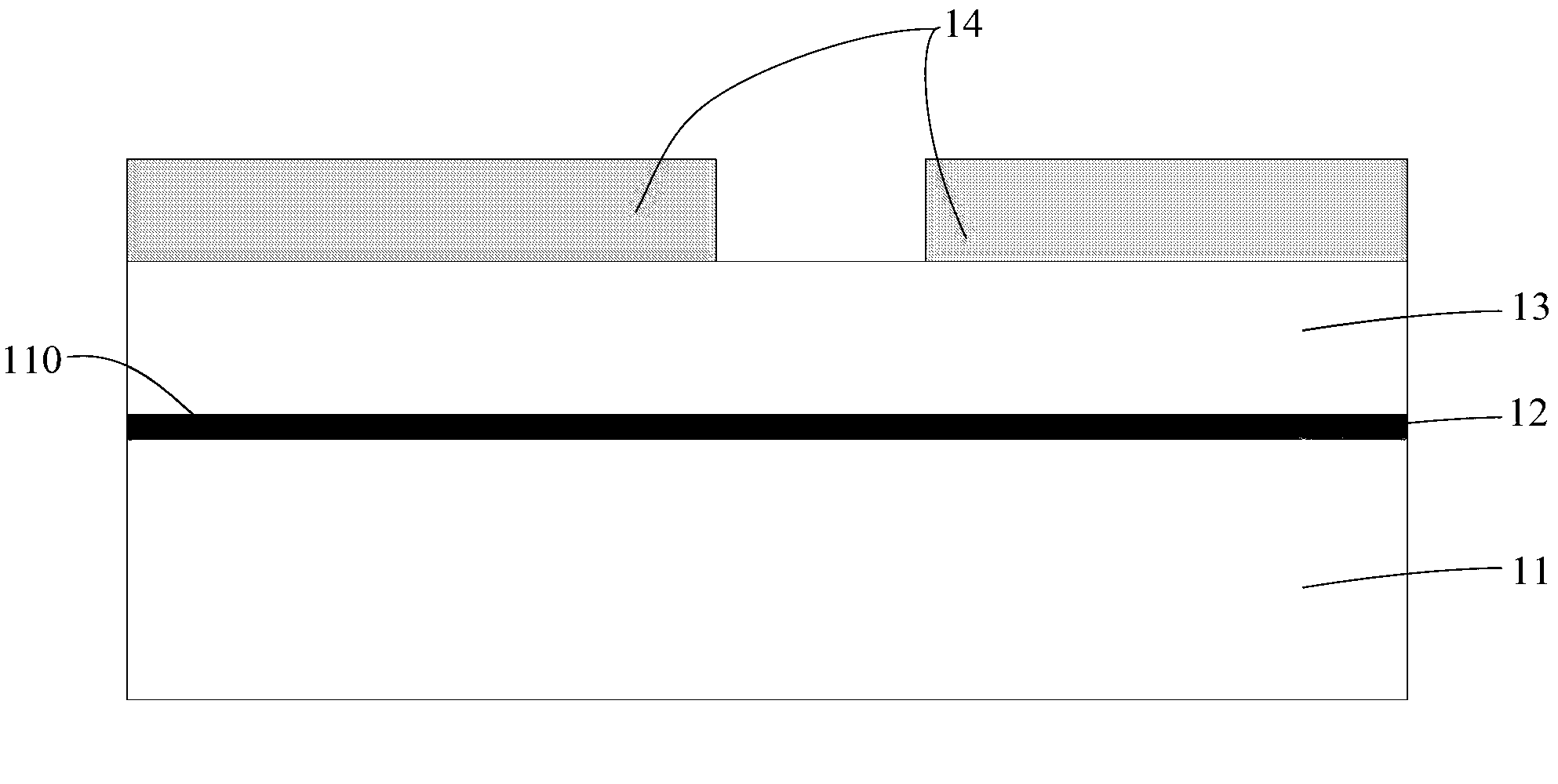
[0026] Please refer to figure 1 , the metal-ceramic composite substrate includes a metal base 11, a ceramic layer 13 disposed on the first surface 110 of the metal base 11, a metal circuit layer 14 disposed on the surface of the ceramic layer 13 away from the first surface 110, and a metal circuit layer 14 through the metal base 11 The metal-ceramic transition layer 12 is formed by injecting nitrogen on the first surface 110 and is connected to the ceramic layer 13. The ceramic layer 13 is composed of a ceramic film and is located between the metal-ceramic transition layer 12 and the metal circuit layer 14. The metal-ceramic transition layer 12 is a mixture of metal and metal nitride.

[0027] The material of the metal base 11 may be aluminum, aluminum alloy, magnesium alloy, titanium alloy, nickel alloy, steel and copper alloy, zinc alloy, lead or titanium-aluminum intermetallic compound and the like. When in use, the material of the metal matrix 11 can be selected according...

Embodiment 2

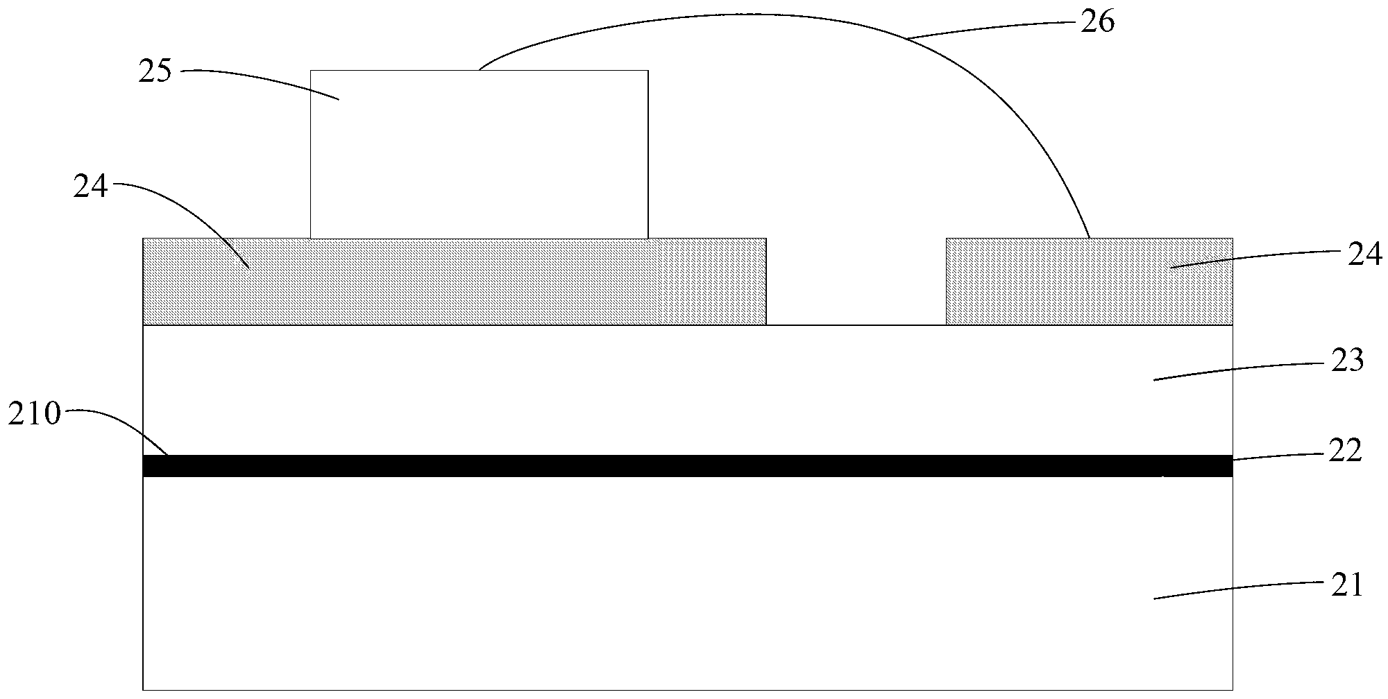
[0035] Please refer to figure 2, the metal-ceramic composite substrate includes a metal base 21, a ceramic layer 23 disposed on the first surface 210 of the metal base 21, a metal circuit layer 24 disposed on the surface of the ceramic layer 23 away from the first surface 210, and a metal circuit layer 24 through the metal base 21 The metal-ceramic transition layer 22 is formed by injecting nitrogen into the first surface 210 of the first surface 210 and is connected to the ceramic layer 23. The ceramic layer 13 is composed of a ceramic film and is located between the metal-ceramic transition layer 22 and the metal circuit layer 24. The metal-ceramic transition layer 22 is a mixture of metal and metal nitride.

[0036] The material of the metal base 21 may be aluminum, aluminum alloy, magnesium alloy, titanium alloy, nickel alloy, steel and copper alloy, zinc alloy, lead or titanium-aluminum intermetallic compound, and the like. During use, the material of the metal matrix 2...

Embodiment 3

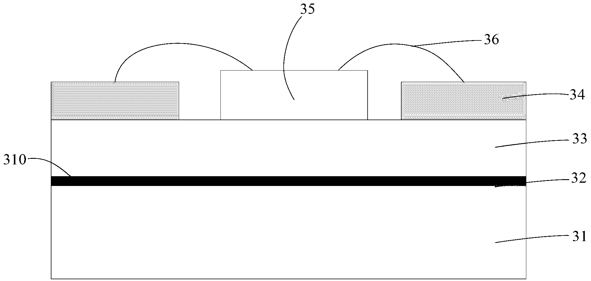
[0047] The difference between this embodiment and the second embodiment is:

[0048] The heating element 35 of this embodiment is installed on the ceramic layer 33, that is, the heating element 35 and the metal circuit layer 34 are arranged side by side on the ceramic layer 33 to form a circuit layer, so the ceramic layer 33 is located between the circuit layer and the circuit layer. between the cermet transition layers 32 .

[0049] The heating element 35 in this embodiment is a light-emitting diode with a horizontal electrode structure.


PUM

PropertyMeasurementUnit
Thicknessaaaaaaaaaa
Thermal conductivityaaaaaaaaaa
Thicknessaaaaaaaaaa

Abstract

The invention is applied to the field of substrates, provides a metal ceramic composite substrate and a manufacturing method for the same, and aims to solve the problems of low thermal conductivity of a metal substrate and low bonding properties of a metal ceramic composite substrate in the prior art. The metal ceramic composite substrate comprises a metal substrate, a ceramic layer, a metal line layer and a metal ceramic transition layer, wherein the ceramic layer is arranged on the metal substrate; the metal line layer is arranged on the surface of the ceramic layer; the metal ceramic transition layer is formed on the metal substrate, and is connected with the ceramic layer; the ceramic layer is positioned between the metal ceramic transition layer and the metal line layer; the metal ceramic transition layer consists of metal and metal nitrides; and the ceramic layer consists of a ceramic thin film. The ceramic layer is used for improving the thermal conductivity of the substrate, and the metal ceramic transition layer is arranged to improve the bonding properties between the ceramic layer and the metal substrate to improve bonding reliability.

Description

technical field [0001] The invention belongs to the field of substrates, in particular to a metal-ceramic composite substrate and a manufacturing method thereof. Background technique [0002] With the development of high-power and high-density electronic devices, the problem of heat dissipation of electronic devices has become increasingly prominent. Especially in recent years, the application of high-power semiconductor lighting devices, such as light-emitting diodes (LEDs), makes it extremely important to solve the problem of heat dissipation. Since the LED spectrum does not contain infrared parts, the heat generated by the LED chip can only be dissipated through the substrate in the form of heat conduction. [0003] Usually, these electronic devices are generally installed on circuit boards with insulating substrates, for example, metal-based copper-clad laminates that use epoxy resin with low thermal conductivity as insulation and bonding layers, the heat dissipation ef...

Claims


Application Information

Patent Timeline
IPC IPC(8): H05K1/02H05K1/05H05K3/00H01L33/62H01L33/54
CPCH01L2224/48091H01L2224/48227H01L2924/00014
Inventor 王新中廖秋荣董山山杨向红
Owner SHENZHEN HOYOL OPTO ELECTRONICS
Why Eureka
Try Eureka