
Continuous roll of optical function film, method of manufacture of liquid crystal display element employing same, and optical function film laminating device

A technology for liquid crystal display elements and optical functions, applied in the field of continuous rolls, can solve the problems of complicated device control, shorten production takt time, etc., and achieve the effect of shortening processing time

Active Publication Date: 2013-05-01
NITTO DENKO CORP
View PDF15 Cites 9 Cited by
  • Summary
  • Abstract
  • Description
  • Claims
  • Application Information

AI Technical Summary

Problems solved by technology

On the other hand, since the cutting process of half-cutting by the cutting device 403 and the bonding process of bonding the optical functional film 310 and the liquid crystal panel W by the bonding device 405 are performed in series, there is a problem that the control of the device is complicated. question
In addition, in the cutting process, it is necessary to stop the conveyance of the film, cut it, and resume the conveyance, so this cutting process becomes a bottleneck for shortening the tact time.

Method used


Image

  • Continuous roll of optical function film, method of manufacture of liquid crystal display element employing same, and optical function film laminating device
  • Continuous roll of optical function film, method of manufacture of liquid crystal display element employing same, and optical function film laminating device
  • Continuous roll of optical function film, method of manufacture of liquid crystal display element employing same, and optical function film laminating device

Examples


Embodiment

[0128] The following examples are given to describe the present invention, but the present invention is not limited to the following examples.

manufacture example 1A

[0131] A norbornene-based film (manufactured by JSR, trade name "ARTON FILM FEKV150D0") with a thickness of 150 μm was used as a base material, and polyvinyl alcohol resin (manufactured by Nippon Gosei, trade name "GOHSENOL NH-18") was coated on the base material. Aqueous solution (solid content concentration 10%), so that the thickness after drying is 21.5 μm, using a tenter stretcher at 143 ° C in the width direction to uniaxially stretch to 4.3 times in the width direction, and forming a polyvinyl alcohol film on the substrate of stacks. The laminate was sequentially immersed in four baths under the following conditions [1] to [4] while being transported, and the polyvinyl alcohol film was swelled, dyed, crosslinked, and washed. Thus, a laminate in which the iodine-dyed polyvinyl alcohol film (polarizing plate) was formed on the substrate was obtained.

[0132] [1] Swelling bath: Immerse in pure water at 28°C for 120 seconds

[0133] [2] Dyeing bath: Immerse for 60 second...

manufacture example 1B

[0138] Amorphous polyethylene terephthalate (A-PET) resin was extruded by T-die method at a molding temperature of 270 degrees to produce a substrate film with a thickness of 200 μm. The same aqueous solution of polyvinyl alcohol as used in Production Example 1A was coated on the base material so that the thickness after drying was 30 μm, and then longitudinally uniaxially stretched to 5.3 times in the longitudinal direction at 100° C. by a roll stretcher. , and a laminate in which a polyvinyl alcohol film was formed on a substrate was produced.

[0139] Swelling, dyeing, crosslinking, and washing of the polyvinyl alcohol film were carried out in the same manner as in the aforementioned Production Example 1A while conveying the laminated body. Thus, a laminate in which the iodine-dyed polyvinyl alcohol film (polarizing plate) was formed on the substrate was obtained.

[0140]A norbornene-based film (manufactured by ZEON CORPORATION, trade name "ZEONOR FILM ZB14-55 / 135") was b...


PUM

PropertyMeasurementUnit
tensile modulusaaaaaaaaaa

Abstract

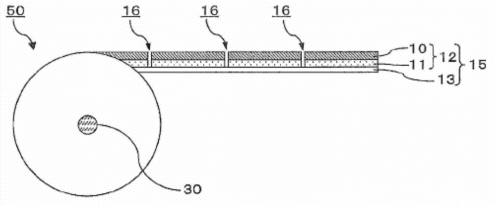
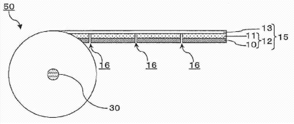
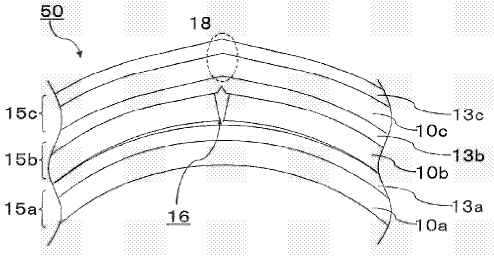
An objective of the present invention is to alleviate striped display distortion that occurs in liquid crystal display elements when taking optical function film from a continuous optical function film roll having cutting lines in the width direction thereof and laminating the optical function film on a liquid crystal panel. This continuous roll has an optical function film layered body (15) in a continuous web shape rolled thereupon, said layered body (15) including at least an optical function film (10) and a carrier film (13) that is detachably layered on the optical function film. The optical film (10) is cut into a plurality of optical function film sheets by cut lines (16) being formed along the width direction of the optical film layered body (15). It is possible to resolve the problem by making the resilience to bending per unit of length of the optical function film in the length direction fall within a prescribed range.

Description

technical field [0001] The present invention relates to a continuous roll in which an optical film laminate in which an optical functional film and a carrier film are laminated is wound up into a roll shape. This invention also relates to the manufacturing method of the liquid crystal display element which unwinds an optical film laminated body from this continuous roll, and bonds this to a liquid crystal panel, and the bonding apparatus used for this manufacturing method. Background technique [0002] A flat panel display represented by a liquid crystal display device is used in a wide range of fields by utilizing features such as thinness, light weight, and low power consumption. A liquid crystal display panel constituting a liquid crystal display device is formed by bonding at least one polarizing film to a liquid crystal cell, and converts a change in the alignment state of liquid crystal molecules due to an electric field through polarized light into a change in viewing...

Claims


Application Information

Patent Timeline
Patent Type & Authority Applications(China)
IPC IPC(8): G02B5/30B65H41/00B65H75/00G02F1/1335
CPCB65H2801/61G02F1/133528B29D11/0073B29D11/00788B65H18/28B65H2301/4127B65H2701/19404B65H41/00G02B5/3033G02B5/30Y10T156/17B65H75/00G02F1/1335
Inventor 平田聪梅本清司近藤诚司中园拓矢
Owner NITTO DENKO CORP
Learn More