
Device used for electrolyzing and processing double-faced trumped-shaped hole array in a thin walled cylinder

A technology of thin-walled cylinders and trumpet holes, which is applied in the direction of electrochemical processing equipment, metal processing equipment, manufacturing tools, etc., can solve the problems of difficult clamping and fixing, difficult realization of stable process conditions, and easy deformation, so as to achieve small deformation of the workpiece and The effect of uniform force, accelerated flow and renewal

Inactive Publication Date: 2013-05-08
HENAN POLYTECHNIC UNIV
View PDF7 Cites 5 Cited by
  • Summary
  • Abstract
  • Description
  • Claims
  • Application Information

AI Technical Summary

Problems solved by technology

[0005] The purpose of the present invention is to provide a device for electrolytically machining double-sided horn hole arrays on thin-walled cylinders, which is suitable for electrolytic machining of thin-walled cylindrical workpieces with large aspect ratios, and can solve the problem of thin-walled cylindrical workpieces with large aspect ratios. Difficult to clamp and fix, easy to deform, and difficult to achieve stable process conditions during processing

Method used


Image

  • Device used for electrolyzing and processing double-faced trumped-shaped hole array in a thin walled cylinder
  • Device used for electrolyzing and processing double-faced trumped-shaped hole array in a thin walled cylinder
  • Device used for electrolyzing and processing double-faced trumped-shaped hole array in a thin walled cylinder

Examples


Embodiment Construction

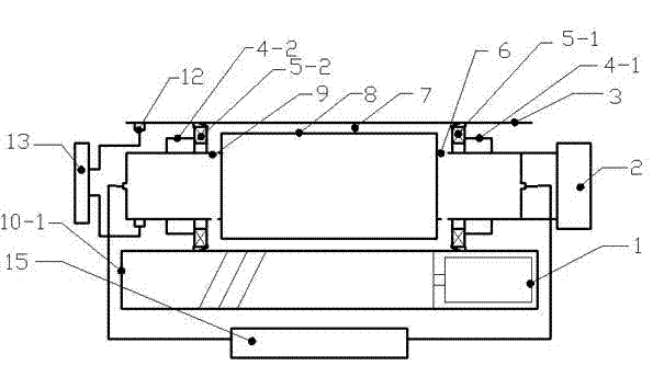
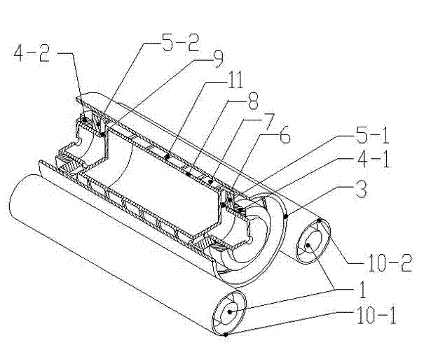
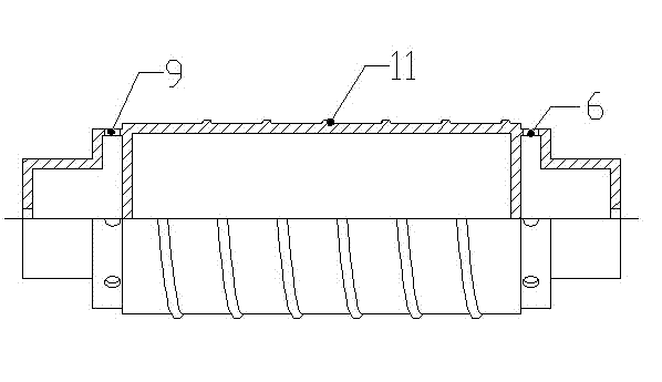
[0022] Such as Figure 1 to Figure 3 As shown, the present invention includes a tool cathode 8, a workpiece anode 3 provided with an electrically insulating adhesive film on the outer surface, a driving device 2 for driving the tool cathode 8 to rotate, an electrolytic machining power source 13, and an electrolyte circulating filter unit 15. The tool cathode 8 is a hollow cylinder provided with a liquid inlet hole 9 and a liquid outlet hole 6, and the outer surface of the tool cathode 8 is provided with one or more spiral protrusions 11, and the workpiece anode 3 is coaxially arranged on the tool in a non-contact manner. Outside the cathode 8, the gap between the spiral protrusion 11 provided on the outer surface of the tool cathode 8 and the inner wall of the workpiece anode 3 is 0.1mm-3mm, and the two ends of the annular cavity 7 formed between the tool cathode 8 and the workpiece anode 3 pass through The electric insulation dynamic seals 5-1, 5-2 are dynamic seals, the oute...


PUM


Abstract

The invention discloses a device used for electrolyzing and processing a double-faced trumped-shaped hole array in a thin walled cylinder. A tool negative pole is a hollow rotary cylinder which is provided with a liquid inlet hole and a liquid outlet hole. A workpiece positive pole, an axis and an non-contact ground sleeve are arranged on the outside of the tool negative pole. Two ends of a ringlike cavity formed between the tool negative pole and the workpiece positive pole are in motive seal through electric insulation motive seal pieces. Two ends of the tool negative pole are respectively connected with an electrolyte circulating filtration unit. A positive pole and a negative pole of an electrochemical machining power supply are respectively connected with the workpiece positive pole and the tool negative pole. Two carrier rollers which are parallelly arranged below the workpiece positive pole are in line contact with the workpiece positive pole. The carrier rollers are driven by a power source unit. Two parallel carrier rollers are used for supporting and locating the large draw ratio thin walled cylinder stably and reliably, workpieces have small deformation, the workpiece positive pole is in a rotary state in the process of processing, electrolytes in a small hole of the workpiece positive pole can drop automatically under the effect of gravity, thus benefiting removal of electrolysates in a blind hole and update of the electrolytes in the small hole.

Description

technical field [0001] The invention relates to an electrolytic machining device, in particular to a device for electrolytic machining of a double-sided horn hole array on a thin-walled cylinder. Background technique [0002] At present, in the fields of metallurgy, chemical industry, powder, biomedicine, automobile, mining, food and beverage, machinery, textile, papermaking, oil and gas and water treatment, aerospace and other fields, it is often applied to the filtration and screening process of substances. The application effect of filtration and sieving largely depends on the technical performance index of the filter (sieve) mesh. The application practice shows that the filter (screen) mesh with double-sided trumpet-shaped hole cross-section has the advantages of small accumulation pressure on the surface of the filter mesh, easy slag unloading and cleaning, not easy to block, long filtration cycle and service life, and easy maintenance. New development trend of high-pe...

Claims


Application Information

Patent Timeline
IPC IPC(8): B23H3/00B23H9/14
Inventor 明平美王俊涛曹淑娟李章东郝巧玲包晓慧苏阳阳毕向阳张延辉聂子超李二静王贝
Owner HENAN POLYTECHNIC UNIV
Learn More