Unlock instant, AI-driven research and patent intelligence for your innovation.
Air cooling system for horizontal vacuum high-pressure air quenching
What is Al technical title?
Al technical title is built by PatSnap Al team. It summarizes the technical point description of the patent document.
An air-cooling system, high-pressure gas technology, applied in the direction of quenching agent, quenching device, heat treatment equipment, etc., can solve the problems of fast cooling of external workpiece, slow cooling of workpiece, slow cooling of internal workpiece, etc., to improve cooling uniformity, The effect of reducing workpiece deformation
Inactive Publication Date: 2020-04-21
BEIJING RES INST OF MECHANICAL&ELECTRICAL TECH
View PDF4 Cites 0 Cited by
Summary
Abstract
Description
Claims
Application Information
AI Technical Summary
This helps you quickly interpret patents by identifying the three key elements:
Problems solved by technology
Method used
Benefits of technology
Problems solved by technology
In the case of multi-workpiece loading, the 360° jet cooling along the circumferential direction will easily cause the external workpiece to cool quickly and the internal workpiece to cool slowly; while the one-way jet cooling of the airflow will gradually slow down the cooling speed of the workpiece along the airflow direction
[0004] The above two cooling methods are easy to cause uneven structure and performance on both sides of a single workpiece and between different workpieces, and large deformation of the workpiece
Method used
Image
Click on the blue label to locate the original text in one second.
Reading with bidirectional positioning of images and text.
Examples
specific Embodiment approach
[0022] The air-cooling system for horizontal vacuum high-pressure gas quenching of the present invention, its preferred embodiment is:
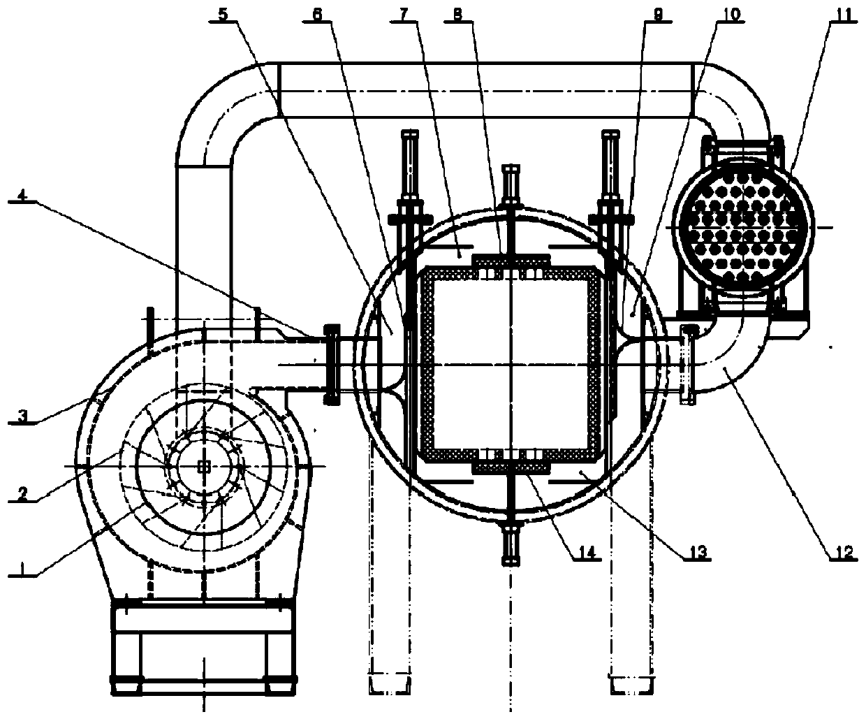
[0023] Including fan, impeller, volute, air inlet pipe, air inlet duct, damper I, upper air duct, upper small heat shield, damper II, return air duct, heat exchanger, return air duct, lower air duct, lower small heat shield;
[0024] The impeller is a centrifugal impeller, which is connected with the fan output shaft and installed in a volute, and the volute has an inlet and an outlet;
[0025] One end of the air inlet pipeline is connected with the outlet of the volute, and the other end is connected with the air inlet of the furnace shell;
[0026] Described air inlet channel is surrounded by the inwall of coaming plate, damper 1, furnace shell and forms cavity, and this cavity is connected with described air inlet pipeline, upper air channel and lower air channel;
[0027] The upper air channel is surrounded by a coaming plate, the inner...
specific Embodiment
[0038] figure 1 Shown is the heating process. At this time, the driving cylinders of the upper small heat shield 8 and the lower heat shield 14 are in the ejected state, and the ventilation holes on both sides of the furnace are closed. When heating in this case, since a closed shell is formed in the furnace, it has good heat preservation and heat insulation effects.
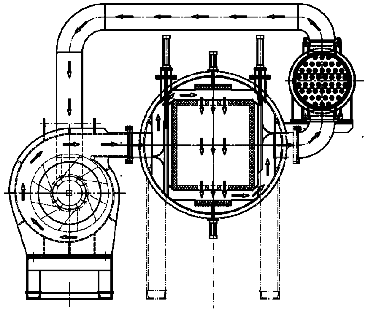
[0039] figure 2 and image 3 Shown is the cooling process, in which the furnace is first filled with high-pressure gas and the fan is started.
[0040] figure 2 Shown is a schematic diagram of airflow cooling from top to bottom. In the figure, the driving cylinders of the upper small heat shield 8, the lower small heat shield 14, and the damper II9 are in the retracted state, and the driven cylinder of the damper I6 is in the ejected state. At this time, the upper small heat shield 8 and the lower heat shield 14 are separated from the furnace, and the ventilation holes on the upper and lower sides of the ...
PUM
Abstract
The invention discloses an air coolingsystem for horizontal vacuum high-pressure air quenching. The air coolingsystem comprises a fan, an impeller, a volute, an air inlet pipeline, an air inlet channel, an air door I, an upper air channel, an upper small heat shield, an air door II, an air return channel, a heat exchanger, an air return pipeline, a lower air channel, a lower small heat shield and the like. The heat exchanger is arranged in a closed shell on an outer side of a furnace body and is connected in series in the air return pipeline; the upper small heat shield and the lower small heat shield are of translation structures and are driven by a cylinder, and the upper small heat shield and the lower small heat shield are closed during heating and opened during cooling; the air doorI and the air door II are installed in the air inlet channel and the air return channel separately, are translation type structures and are driven by the air cylinder. Through the movement of the airdoor I and the air door II, the air inlet channel can be communicated with the upper / lower air channel, and the air return channel is communicated with the lower / upper air channel, so that switchingof cooling airflow directions in the air quenching process is realized. And the cooling uniformity in the gas quenching process is improved, so that the uniformity of the structure and performance ofa workpiece is improved, and the deformation of the workpiece is reduced.
Description
technical field [0001] The invention relates to an air-cooling system for vacuum high-pressure gas quenching, in particular to an air-cooling system for horizontal vacuum high-pressure gas quenching which can realize alternate cooling of airflow up and down. Background technique [0002] Heat treatment is a process technology that gives or improves the service performance of the workpiece by changing the microstructure inside the workpiece, or changing the chemical composition of the workpiece surface, and fully exploits the potential of the material. Vacuum high-pressure gas quenching is a heat treatment technology developed in recent years. It uses inert gases such as high-purity nitrogen or argon as the quenching cooling medium. It has the advantages of cleanness, no pollution, no need for subsequent cleaning, and easy adjustment of quenching strength. It is widely used in aerospace, military industry, automobile and other fields. [0003] At present, vacuum high-pressur...
Claims
Application Information
Patent Timeline
Application Date:The date an application was filed.
Publication Date:The date a patent or application was officially published.
First Publication Date:The earliest publication date of a patent with the same application number.
Issue Date:Publication date of the patent grant document.
PCT Entry Date:The Entry date of PCT National Phase.
Estimated Expiry Date:The statutory expiry date of a patent right according to the Patent Law, and it is the longest term of protection that the patent right can achieve without the termination of the patent right due to other reasons(Term extension factor has been taken into account ).
Invalid Date:Actual expiry date is based on effective date or publication date of legal transaction data of invalid patent.
IPC IPC(8): C21D1/767C21D1/613C21D1/62
CPCC21D1/613C21D1/62C21D1/767
Inventor 陆文林丛培武杜春辉尹承锟何龙祥王同陈旭阳薛丹若杨广文范雷
Owner BEIJING RES INST OF MECHANICAL&ELECTRICAL TECH

