Eureka AIR delivers breakthrough ideas for toughest innovation challenges, trusted by R&D personnel around the world.

Steam Rankine-ammonia vapor Rankine combined cycle power generation device

A technology of Rankine cycle and ammonia steam, applied in the direction of steam engine device, steam generation, steam application, etc., to achieve the effect of improving absolute thermal efficiency, improving thermal efficiency, avoiding pollution and loss of steam water

Active Publication Date: 2013-05-08
NANJING RECLAIMER ENVIRONMENTAL TEKNIK
View PDF12 Cites 2 Cited by
  • Summary
  • Abstract
  • Description
  • Claims
  • Application Information

AI Technical Summary

Problems solved by technology

[0008] The purpose of the present invention is to solve the shortcomings of the above-mentioned steam Rankine cycle and Karina cycle and other technologies, and propose a steam Rankine-ammonia steam Rankine combined cycle power generation device, which can replace the traditional steam Rankine cycle unit and solve the problem at the same time The key issues of the safe operation of the ammonia steam Rankine cycle unit and the recovery of a large amount of latent heat of vaporization released during the condensation of the steam in the condenser are solved, and the positive pressure operation mode of the condenser is adopted to recover the vaporization of the steam condensed in the steam Rankine cycle The latent heat is used for low-temperature end ammonia steam Rankine cycle power generation, so as to effectively improve the thermal efficiency of the entire combined cycle unit, and finally achieve the purpose of saving energy and reducing consumption, and improving the thermal efficiency of the system

Method used


Image

  • Steam Rankine-ammonia vapor Rankine combined cycle power generation device

Examples


Embodiment 1

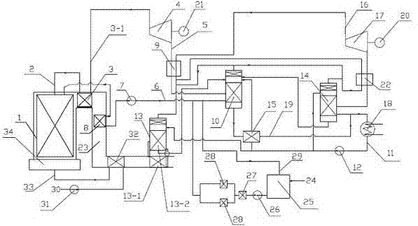
[0044] like figure 1 Shown, a kind of steam Rankine-ammonia steam Rankine combined cycle power plant, this device comprises steam Rankine cycle, ammonia steam Rankine cycle system, specific embodiment is as follows:

[0045] The ammonia steam Rankine cycle uses a mixture of ammonia and water.

[0046] The steam Rankine cycle refers to the saturated steam 2 coming out of the boiler body 1, passing through the heater 3 to form superheated steam 3-1, and sending it into the steam turbine 4 to drive the steam generator 21 to generate electricity; the exhaust steam 5 coming out of the steam turbine 4 passes through Heater 9 and condensing evaporator 10 form condensed water 6, and condensed water 6 passes through feed water pump 7, feed water heater 8, and boiler body 1 to generate saturated steam, thereby forming a steam Rankine cycle.

[0047] In the ammonia vapor Rankine cycle, the condensation evaporator 10, the cooling evaporator 12, and the ammonia evaporator 14 are operated...


PUM


Abstract

The invention relates to a steam Rankine-ammonia vapor Rankine combined cycle power generation device. Ammonia vapor in an ammonia vapor Rankine cycle is used for cooling steam in a steam Rankine cycle. Latent heat of vaporization of the steam in the steam Rankine cycle is recovered for power generation of the ammonia vapor Rankine cycle, and therefore the steam Rankine and the ammonia vapor Rankine cycle are compounded together to form an enforceable combined cycle device. At the same time, safety problem of recovering of waste heat of exhaust gas of the ammonia vapor Rankine cycle is solved, exhaust gas temperature is effectively reduced, low-temperature corrosion of the exhaust gas is avoided, and the exhaust gas, waste water and the waste heat of exhaust steam of a steam Rankine cycle system can be effectively recovered and utilized. The steam Rankine-ammonia vapor Rankine combined cycle power generation device not only can be used for energy conservation improvement on an existing machine unit, but also can be used for designing and building a newly built machine unit, is especially suitable for new construction, extending construction and reconstruction of a power unit in water-deficient areas, power shortage areas and other areas, and therefore the Britten-steam Rankine-ammonia vapor Rankine combined cycle power generation device has remarkable economic, social and environmental protection benefits.

Description

technical field [0001] The invention relates to a steam Rankine-ammonia steam Rankine combined cycle power generation device, specifically belonging to the technical field of thermal power plant power devices. Background technique [0002] A thermal power plant that uses water vapor as a working medium is a large-scale factory that converts thermal energy into mechanical energy, and then converts mechanical energy into electrical energy. The cycle applied in power plants is very complicated, but in essence, it is mainly completed by the Rankine cycle composed of boilers, steam turbines, condensers, water pumps and other equipment. The working principle is: the feed water is first pressurized by the feed water pump and then sent Into the boiler, the water in the boiler is heated and vaporized to form high-temperature and high-pressure superheated steam. The superheated steam expands and does work in the steam turbine and becomes low-temperature and low-pressure exhaust steam....

Claims


Application Information

Patent Timeline
Patent Type & Authority Applications(China)
IPC IPC(8): F01K23/10F01K25/10F01K17/02F27D17/00F22D11/06
CPCY02E20/16Y02P10/25
Inventor 王海波
Owner NANJING RECLAIMER ENVIRONMENTAL TEKNIK
Why Eureka
Eureka Blog
Learn More