Floating type lithium niobate optical waveguide

A technology of lithium niobate and optical waveguide, which is applied in the direction of optical waveguide, light guide, optics, etc., can solve the problems of reducing transmission loss and difficulty in processing lithium niobate crystals with different ratios, so as to achieve reduced transmission loss, low transmission loss, Improve the effect of transmission efficiency

Inactive Publication Date: 2013-05-08
东北大学秦皇岛分校
View PDF5 Cites 10 Cited by
  • Summary
  • Abstract
  • Description
  • Claims
  • Application Information

AI Technical Summary

Problems solved by technology

[0004] Aiming at the problem that the difference in the refractive index contrast of traditional lithium niobate optical waveguides in the market is too small (n is only about 0.1) and the traditional etching method is difficult to process lithium niobate crystals, the present invention proposes a suspended lithium niobate optical waveguide The waveguide, the suspended lithium niobate optical waveguide, etch the lithium niobate sample by using helium (He) ion implantation, focused ion beam (focused ion beam) etching, wet etching (wet etching) and other techniques Processing, and finally a suspended optical waveguide structure is obtained, so that the upper and lower sides of the waveguide area are air (refractive index = 1), and the refractive index difference between the waveguide area and the surrounding restricted area is maximized (n = 2.3-1 = 1.3 ), where 2.3 is the refractive index of lithium niobate, and 1 is the refractive index of air, so that the light is well restricted during the propagation process, thereby greatly reducing the transmission loss, thereby maximizing the working efficiency of the device

Method used


Image

  • Floating type lithium niobate optical waveguide
  • Floating type lithium niobate optical waveguide
  • Floating type lithium niobate optical waveguide

Examples


Embodiment

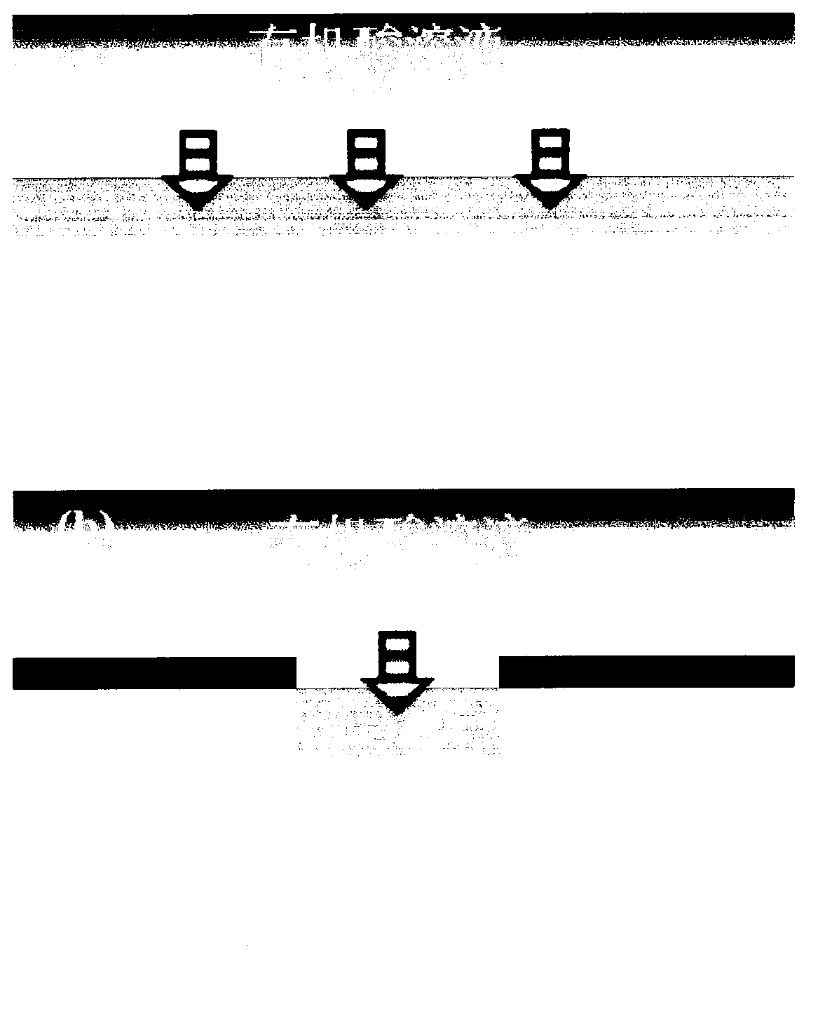
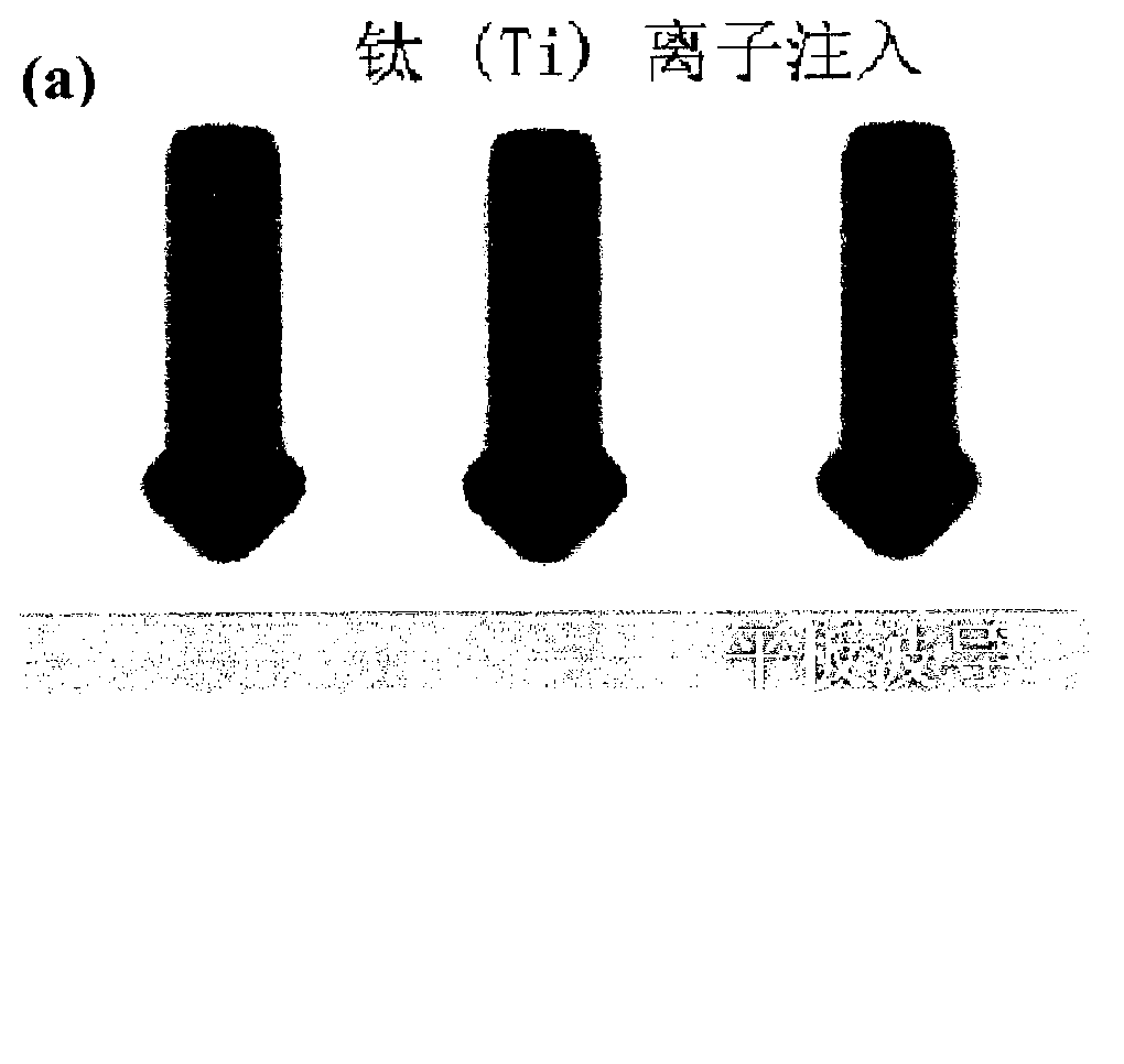
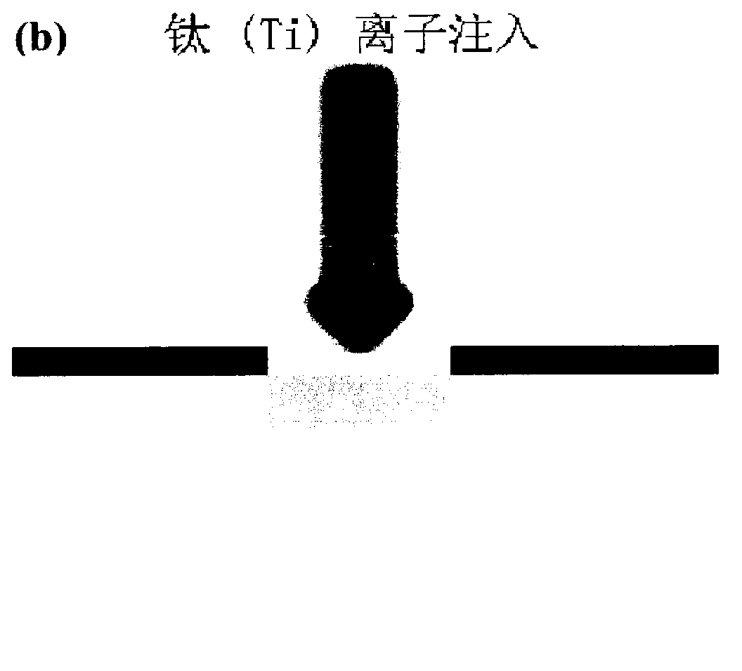
[0027] Example: see attached Figure 6 , Suspended lithium niobate optical waveguide, characterized in that: select lithium niobate sample as the substrate and operate according to the following steps, first, use a helium ion (He+) beam with an energy of 1 megaelectron volt (MeV) to bombard lithium niobate In the sample, lattice damage is formed in a certain area under the sample surface, and the portion where the lattice damage is formed has a refractive index smaller than the portion without damage, so a difference in refractive index can be formed, and then a waveguide is formed to confine the beam to propagate in the waveguide area. However, similar to the traditional proton exchange and titanium diffusion methods, the refractive index contrast difference caused by the lattice damage caused by helium ion bombardment is small, especially in the vertical direction, where light can easily leak to the substrate during transmission. direction and dissipate to form losses. The ...


PUM

PropertyMeasurementUnit
refractive indexaaaaaaaaaa

Abstract

The invention relates to a floating type lithium niobate optical waveguide. A lithium niobate sample is adopted as base material, and operation is carried out according to the following steps of bombarding the lithium niobate sample with a helium ion (He+) beam which is 1 Mev in energy, forming crystal lattice damage in a certain area below the surface of the sample, enabling the parts with the crystal lattice damage to be provided with refractive index smaller than that of undamaged parts, limiting a light beam in a waveguide area to spread, etching round or rectangular holes in the surface of the sample in a focused ion beam etching way, enabling mixed acid solutions to be contacted with the parts with the crystal lattice damage through the holes, further corroding the parts, forming an air interlayer, and forming a floating waveguide structure on the surface of the lithium niobate sample. The lithium niobate optical waveguide plays a good role in limiting optical signals spreading in the lithium niobate optical waveguide, has extremely low transmission loss, and can be widely used for electronic components, optical components and modulation components.

Description

technical field [0001] The invention belongs to an optical waveguide material, in particular to a lithium niobate optical waveguide material with a suspended structure. Background technique [0002] Lithium niobate (LiNbO 3 ) crystal is one of the most widely used new inorganic materials at present. It is a good piezoelectric transducer material, ferroelectric material, electro-optic material, nonlinear optical material and surface wave matrix material. Lithium niobate, as a material with electro-optic effect, plays a light modulation role in optical communication and is widely used. The so-called electro-optic effect refers to the effect that the refractive index of the crystal changes when an electric field is applied to the crystal. Some crystals have intrinsic electric dipole moments due to spontaneous polarization. When an electric field is applied to such crystals, the external electric field will make the orientation of the intrinsic dipole moments in the crystal te...

Claims


Application Information

Patent Timeline
Patent Type & Authority Applications(China)
IPC IPC(8): G02B6/122G02B6/13G02F1/355
CPCG02B6/122G03F7/00G02B6/13G02B6/00G02F2201/063G02B6/1225G02B6/136G02B2006/121
Inventor 姜潇潇司光远吕江涛谷琼婵马振鹤王凤文
Owner 东北大学秦皇岛分校
Why Eureka
Try Eureka