High-hole-density through hole metal foam electronic element heat-dissipation device based on impact jet flow

A metal foam, impinging jet technology, applied in the direction of electric solid devices, electrical components, semiconductor devices, etc., can solve the problem that the heat exchange performance of through-hole metal foam through-hole metal foam cannot be fully utilized, the specific heat capacity of the refrigerant is small, and the refrigerant is easy to leak. and other problems, to achieve the effect of increasing the heat transfer coefficient, increasing the heat transfer coefficient, and enhancing the pulverization effect.

Active Publication Date: 2013-05-22
SHANGHAI JIAO TONG UNIV
View PDF8 Cites 9 Cited by
  • Summary
  • Abstract
  • Description
  • Claims
  • Application Information

AI Technical Summary

Problems solved by technology

However, the specific heat capacity of the refrigerant is small, so the overall heat transfer coefficient of the device is low
Moreover, the refrigerant is easy to leak and pollute the environment.
[0005] In summary, although the existing technology has improved the heat transfer efficiency of the electronic chip cooling device, it cannot make full use of the heat transfer performance of the through-hole metal foam, especially the high-density through-hole metal foam.
The advantages of high-density through-hole metal foam with large specific surface area and strong flow-disturbing ability have not been brought into play

Method used


Image

  • High-hole-density through hole metal foam electronic element heat-dissipation device based on impact jet flow
  • High-hole-density through hole metal foam electronic element heat-dissipation device based on impact jet flow
  • High-hole-density through hole metal foam electronic element heat-dissipation device based on impact jet flow

Examples


Embodiment 1

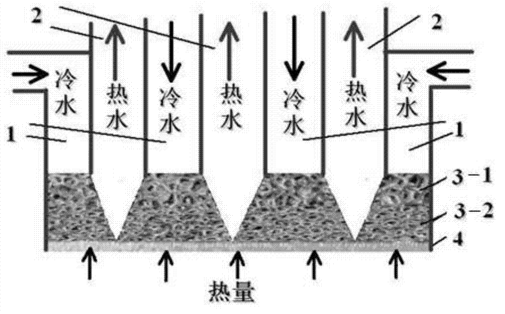
[0027] Such as figure 1 As shown, this embodiment includes: a heat exchange substrate 4, a through-hole metal foam 3 sintered on the heat exchange substrate 4, a cooling water inlet pipe 1 and a drain pipe 2, wherein: the main bodies of the cooling water inlet pipe 1 and the drain pipe 2 are vertical Arranged at straight intervals, the heat exchange part at the bottom of the two water pipes is provided with a through-hole metal foam 3, and the through-hole metal foam 3 has a heat exchange structure at the position where it connects with the drain pipe 2;

[0028] The internal through-holes of the through-hole metal foam 3 have a gradually changing density structure, specifically referring to: the porosity is the same, and the pore density increases or decreases along the vertical direction of the wall; or the pore density is the same, the porosity increases or decreases. decrease; or the hole density and porosity are the same, but the materials constituting the through-hole me...

Embodiment 2

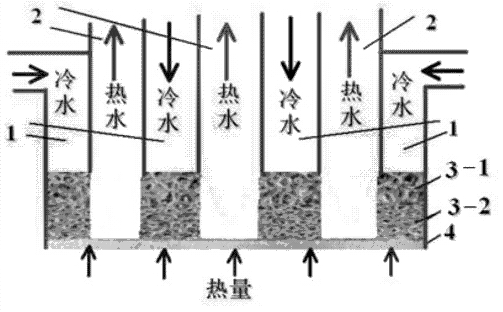
[0044] The same settings as in Example 1, but as figure 2 As shown, the heat exchange structure is a U-shaped symmetrical groove.

Embodiment 3

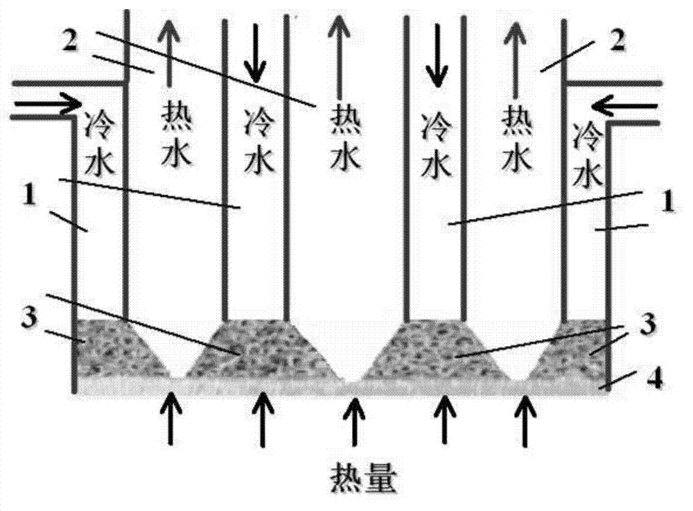
[0046] The same settings as in Example 1, but as image 3 As shown, the through-hole metal foam 3 of this embodiment is a single-layer structure with a simplified structure.


PUM

PropertyMeasurementUnit
Widthaaaaaaaaaa
Thicknessaaaaaaaaaa
Hole densityaaaaaaaaaa

Abstract

A high-hole-density through hole metal foam electronic element heat-exchanging device based on impact jet flow comprises a heat-exchanging substrate, through hole metal foam sintered on the heat-exchanging substrate, a cooling water inlet pipe and a water drainage pipe, wherein main bodies of the cooling water inlet pipe and the water drainage pipe are vertical arranged at intervals, heat-exchanging parts at the bottoms of the two water pipes are provided with the through hole metal foam, and a heat-exchanging structure is arranged in the position wherein the through hole metal foam is connected with the water drainage pipe. According to the high-hole-density through hole metal foam electronic element heat-dissipation device based on the impact jet flow, the through hole metal foam is used for separating the flowing route of supplement liquid and the escape route of bubbles, and largely reduces the resistance when the bubbles escape. The heat-exchanging device is high in heat-exchanging efficiency, and is capable of being widely used in the heat-exchanging field of electronic elements.

Description

technical field [0001] The invention relates to a cooling device in the field of electronic devices, in particular to a high-pore-density through-hole metal foam heat sink for electronic devices based on impinging jets. Background technique [0002] With the development of the electronic industry, the performance of electronic devices is getting higher and higher, and their heating power is also increasing rapidly. The maximum heating power of current electronic chips has exceeded 100W / cm 2 , and is still increasing rapidly. Impingement jet heat transfer is an efficient heat transfer method, and its heat transfer coefficient is 1-2 orders of magnitude higher than that of ordinary natural convection heat transfer. The boiling heat transfer coefficient is 1-2 orders of magnitude higher than that of single-phase heat transfer. High pore density (100PPI-130PPI) through-hole metal foam is a kind of high porosity (0.88-0.98), high specific surface area (10000-13000m 2 / m 3 ) ...

Claims


Application Information

Patent Timeline
IPC IPC(8): H01L23/473G06F1/20
Inventor 徐治国赵长颖王美琴
Owner SHANGHAI JIAO TONG UNIV
Why Eureka
Try Eureka