Motor assembly for vertical axis washer

A washing machine and vertical shaft technology, applied in the field of motor assembly for vertical shaft washing machines, can solve the problems of insufficient compact structure and high cost of motor occupation, and achieve the effects of low production cost, simple assembly process, and low noise

Inactive Publication Date: 2013-05-22
CHANGZHOU YATONG JIEWEI MOTOR
View PDF8 Cites 5 Cited by
  • Summary
  • Abstract
  • Description
  • Claims
  • Application Information

AI Technical Summary

Problems solved by technology

Although this structure further reduces the occupied space to a certain extent, because its principle is to use the inner circumferential space of the stator of the outer rotor motor to install the reduction mechanism in the inner diameter space of the stator through the installation parts, it cannot be used in the inner rotor without inner space. The application on the motor has certain limitations. At the same time, the motor body directly drives the shaft, and then decelerates the drive shaft through the reduction mechanism installed in the inner diameter space of the motor, so it only reduces the occupied space to a certain extent, but the structure It is still not compact enough. Furthermore, when the volume of the reduction mechanism needs to be increased in order to obtain a larger transmission ratio, the outer rotor motor must also increase the volume of the inner diameter to realize this invention. Obviously, this does not solve the essential technical problem
[0004] In addition, the direct connection of the motor and the reduction mechanism in the prior art, in order to meet the starting torque and maximum torque required for the operation of the mechanism, the motor needs to use an external rotor motor, generally a DC brushless or permanent magnet synchronous motor, which requires expensive Permanent magnet materials, resulting in very high cost of motor occupation

Method used


Image

  • Motor assembly for vertical axis washer
  • Motor assembly for vertical axis washer
  • Motor assembly for vertical axis washer

Examples


Embodiment 1

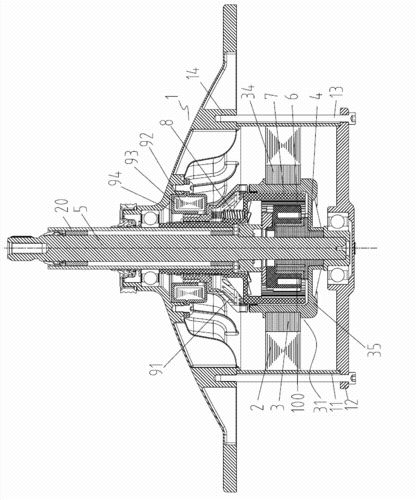
[0074] Example 1 as figure 1 , 2 As shown, it is a structural schematic diagram of the connecting device in the motor assembly for a vertical shaft washing machine of the present invention as a slider structure. Such as figure 1 As shown, the motor in this embodiment is the inner rotor motor described above. Wherein, the housing assembly 1 includes: a cylindrical housing 11 with both ends open, a motor end cover 12 connected to the bottom end of the housing 11 , a mounting plate 14 located at the top of the housing and connected to the motor end cover 12 through motor bolts 13 , and the housing 11, the motor end cover 12 and the mounting plate 14 enclose an internal space for placing other components such as the stator 2 and the inner rotor 3.

[0075] The inner rotor 3 of this embodiment includes a drive frame 31 and a cavity 32 inside the drive frame, and a locking tooth 33 is provided on the top end surface of the drive frame. Specifically, such as figure 1 , Figure ...

Embodiment 2

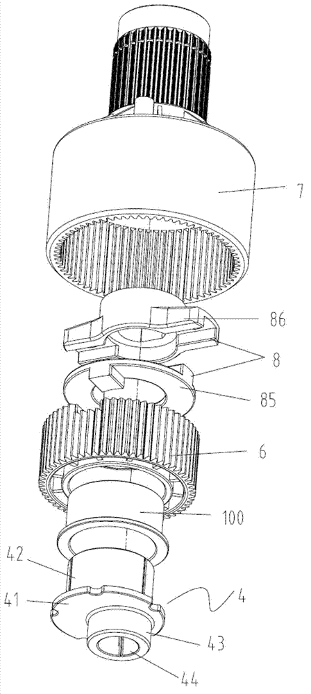
[0106] Example 2 as Figure 7 , 8 As shown, it is a structural schematic diagram of a motor assembly for a vertical shaft washing machine using a connecting plate structure according to the present invention.

[0107] Such as Figure 7 It can be seen that the motor in this embodiment is also the inner rotor motor described above. Wherein, an inner rotor with a cavity is arranged in the housing assembly, and a reduction mechanism is arranged in the cavity of the inner rotor, and the reduction mechanism includes an eccentric sleeve 4, a spur gear 6, an inner ring gear 7 and a connecting device 8, In this embodiment, the connection device adopts a connection plate structure.

[0108] In this embodiment, the inner rotor motor, the housing assembly, the clutch device and the eccentric sleeve and the inner ring gear in the reduction mechanism are all the same as those in Embodiment 1, and will not be repeated here. Only the connection device and the connection device will be desc...

Embodiment 3

[0117] Embodiment 3 Embodiment 3 is a further preferred embodiment of Embodiment 1 and Embodiment 2. In order to improve the washing effect, this embodiment provides a washing method using a hysteresis damper and its application to a motor assembly for a vertical shaft washing machine.

[0118] The motor assembly for a vertical shaft washing machine in this embodiment, on the basis of the foregoing, further includes: a hysteresis damper is installed and connected to the outside of the dehydration shaft sleeve, and the hysteresis damper can generate a damping force on the dehydration shaft sleeve, so that the dehydration shaft sleeve The rotation speed of the dehydration sleeve is equal to or less than the rotation speed of the washing shaft,

[0119] Such as Figure 14 It can be seen that the motor in this embodiment is also the inner rotor motor described above. Wherein, an inner rotor with a cavity is arranged in the housing assembly, and a reduction mechanism is arranged i...


PUM


Abstract

The invention relates to a motor assembly for a vertical axis washer. The vertical axis washer comprises a wash actuator fixedly connected with a wash shaft and a dewatering actuator fixedly connected with a dewatering shaft sleeve. The motor assembly comprises a motor, a reduction mechanism connected with the motor, the wash shaft, the dewatering shaft sleeve, and a clutch device, wherein the wash shaft and the dewatering shaft sleeve are connected with the reduction mechanism and the clutch device is used for switching washing and dewatering modes. The motor assembly is characterized in that the motor is an eight-pole induction motor. The eight-pole induction motor comprises a stator component and a rotor component mounted within the stator component. Rotation axis of the rotor component overlaps with axis of the wash shaft. The motor assembly fully satisfies maximum torque and starting torque required by mechanism operation, enables manufacturing cost to be greatly lowered and is low in noise.

Description

technical field [0001] The invention relates to a motor assembly for a vertical shaft washing machine. Background technique [0002] Ordinary motors have a high speed. In order to obtain a suitable output speed, the motor needs to be decelerated in practical applications. At present, the commonly used method is to transmit the motor to the reducer and decelerate through the first-stage pulley, and set a first-stage pulley in the reducer. Or multi-stage gear reduction mechanism to complete the deceleration of a certain speed ratio. This structure is not only complicated, but also takes up a lot of space. In order to solve this technical problem, there are currently some proposals to remove the pulley and directly connect the motor and the reducer. Since the motor body and the reducer are still relatively independent, the motor body and the reducer need to occupy installation space respectively, and the structure is not enough. Compact and still bulky. [0003] In order to ...

Claims


Application Information

Patent Timeline
Patent Type & Authority Applications(China)
IPC IPC(8): H02K17/32H02K17/06H02K17/14H02K5/04D06F37/30
Inventor 陈道超
Owner CHANGZHOU YATONG JIEWEI MOTOR
Why Eureka
Try Eureka