
Light-emitting diode (LED) lamp and preparation method thereof

A technology of LED lamp beads and LED bulbs, applied in lighting and heating equipment, cooling/heating devices of lighting devices, point light sources, etc., can solve the problems of poor thermal conductivity, reduced mechanical properties, high production costs, etc., and achieve production efficiency High thermal conductivity and low production cost

Inactive Publication Date: 2015-05-06
中山市欧点照明有限公司
View PDF7 Cites 0 Cited by
  • Summary
  • Abstract
  • Description
  • Claims
  • Application Information

AI Technical Summary

Problems solved by technology

At present, most of the research on filling thermally conductive plastics adopts the method of physical filling, which has poor thermal conductivity, serious decline in mechanical properties, and high production costs.

Method used


Image

  • Light-emitting diode (LED) lamp and preparation method thereof
  • Light-emitting diode (LED) lamp and preparation method thereof
  • Light-emitting diode (LED) lamp and preparation method thereof

Examples


Embodiment 1

[0074] Embodiment 1: The ABS used in the embodiment of the present invention is a terpolymer of acrylonitrile, butadiene and styrene, A represents acrylonitrile, B represents butadiene, and S represents styrene; wherein, acrylonitrile accounts for 25% ~30%, butadiene accounts for 16%~28%, and styrene accounts for 45%~60%.

[0075] The high thermal conductivity nanocomposite plastic of the present invention, the filler included in the preparation raw material is one or more of the following compounds (or mixtures): MgO, Al 2 o 3 、Si 3 N 4 , BN, high-purity carbon powder, AlN, ZnO, KAl(SO 4 ) 2 12H 2 O (alum), Al 2 o 3 -2SiO2 2 -2H 2 O (kaolin).

Embodiment 2

[0076] Embodiment 2: The MgO used in the embodiment of the present invention is nano MgO particles.

[0077] The industrial production process of nano powder materials requires simple preparation methods, suitable production costs, good repeatability, uniform powder particle size, high product purity and low agglomeration degree. There are many methods for synthesizing nano-magnesia in the prior art, but few of them can actually be applied to industrial production. One is because of problems such as equipment, cost, raw materials, scale, and investment; the other is that some processes are still in the laboratory research stage, and it is difficult to realize industrialized production, and some are even impossible to realize industrialized production.

[0078] In this example, MgO particles were prepared by a solid-phase method at room temperature.

[0079] The room-temperature solid-phase synthesis method of the present invention overcomes the agglomeration problem existing ...

Embodiment 3-1

[0081] Embodiment 3-1: Si used in the embodiment of the present invention 3 N 4 It is nano-silicon nitride particles and meets the following indicators:

[0082]


PUM

PropertyMeasurementUnit
particle diameteraaaaaaaaaa
densityaaaaaaaaaa
diameteraaaaaaaaaa

Abstract

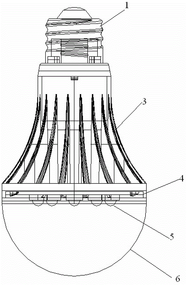
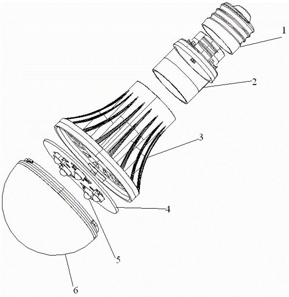
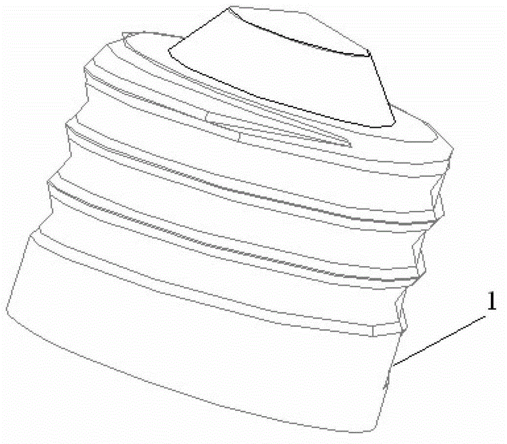
The invention discloses a light-emitting diode (LED) lamp. An LED lamp bead 1 is arranged on a stainless steel substrate 4, one face, provided with an LED lamp bead 5, of the stainless steel substrate 4 is connected with a protective shade 6, the other face of the stainless steel substrate is connected with a radiator 3, and a rotary joint type lamp opening 2 is fixedly connected with a rotary joint groove formed in a lamp seat through a rotary joint device arranged on the rotary joint type lamp opening. The radiator 3 is composed of cooling fins. An arc-shaped structure is adopted in the cooling fins and the cooling fins are evenly distributed. A light transmitting material quality structure is adopted in the protective shade 6. The protective shade 6 is in a semi-spherical shape. By the adoption of the rotary joint type structure in the LED lamp, the LED lamp can resolve the problem in an existing LED lamp, a production assembling method by manual matching of automatic installation and flow line assembly can be used, and the LED lamp has the advantages of being concise in production assembling, high in production efficiency, low in production cost, attractive and firm in connection, good in lighting effect, safe in use, and long in service life.

Description

technical field [0001] The invention relates to the technical field of lighting mechanical devices, in particular to a novel LED lamp and a preparation method thereof. Background technique [0002] The current LED lighting mostly adopts the method of filament connection, which has the problems of cumbersome production steps, long processing time for production parts, and high production cost. In addition, it also has poor thermal conductivity of materials, unsatisfactory stability, and molding, The problem of poor flame retardancy and insulation performance. Therefore, a LED lighting lamp that can solve the above problems is needed. The material can have good thermal conductivity and stability, and can well solve the problem of molding, flame retardancy and insulation Performance problems, while simplifying the assembly method, improving production efficiency, increasing production costs and service life, so as to meet the needs of actual conditions. [0003] Now, as electr...

Claims


Application Information

Patent Timeline
Patent Type & Authority Patents(China)
IPC IPC(8): F21S2/00F21V29/50F21V17/10C08L55/02C08K13/04C08K7/04C08K7/18C08K3/28C08K3/22C08K3/34C08K3/38C08K3/04F21Y101/02F21K9/232F21V29/77F21Y115/10
Inventor 曾晶曾兆永尚朋丘新涛
Owner 中山市欧点照明有限公司
Learn More