Surface coating cutting tool with excellent defect resistance and abrasion resistance

A cutting tool and surface coating technology, applied in the field of surface coating cutting tools, can solve the problems of damaged film surface, decreased defect resistance, easy to fall off, etc.

Active Publication Date: 2013-05-29
MITSUBISHI MATERIALS CORP
View PDF9 Cites 4 Cited by
  • Summary
  • Abstract
  • Description
  • Claims
  • Application Information

AI Technical Summary

Problems solved by technology

Spherical particles or particles that are slender but elongated in the film thickness direction are easily blocked and easy to fall off during cutting, and the film surface is seriously damaged when falling off, so there is a defect resistance due to the increase in surface roughness. subject of sexual decline
Therefore, the following situation arises. I...

Method used


Image

  • Surface coating cutting tool with excellent defect resistance and abrasion resistance
  • Surface coating cutting tool with excellent defect resistance and abrasion resistance
  • Surface coating cutting tool with excellent defect resistance and abrasion resistance

Examples


Embodiment

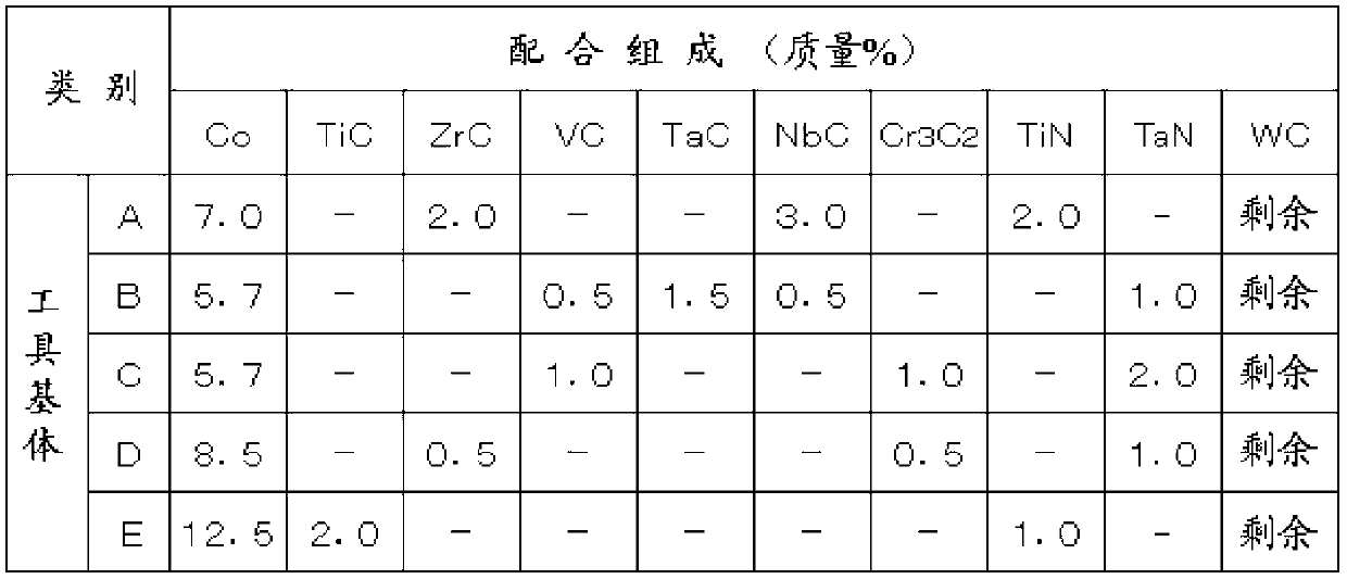
[0052] As raw material powders, WC powder, TiC powder, ZrC powder, VC powder, TaC powder, NbC powder, Cr 3 C 2powder, TiN powder, TaN powder and Co powder, and these raw material powders were mixed into the compound composition shown in Table 1, and paraffin wax was further added and ball milled in acetone for 24 hours. After drying under reduced pressure, ISO·SEEN1203AFTN1 (Hard substrates A to E) Stamping into a green compact of a predetermined shape, vacuum sintering the green compact in a vacuum of 5Pa at a predetermined temperature in the range of 1370-1470°C for 1 hour, after sintering, Tool substrates A to E made of WC-based cemented carbide were manufactured by chamfering the cutting edge portion with a width of 0.15 mm and an angle of 20 degrees.

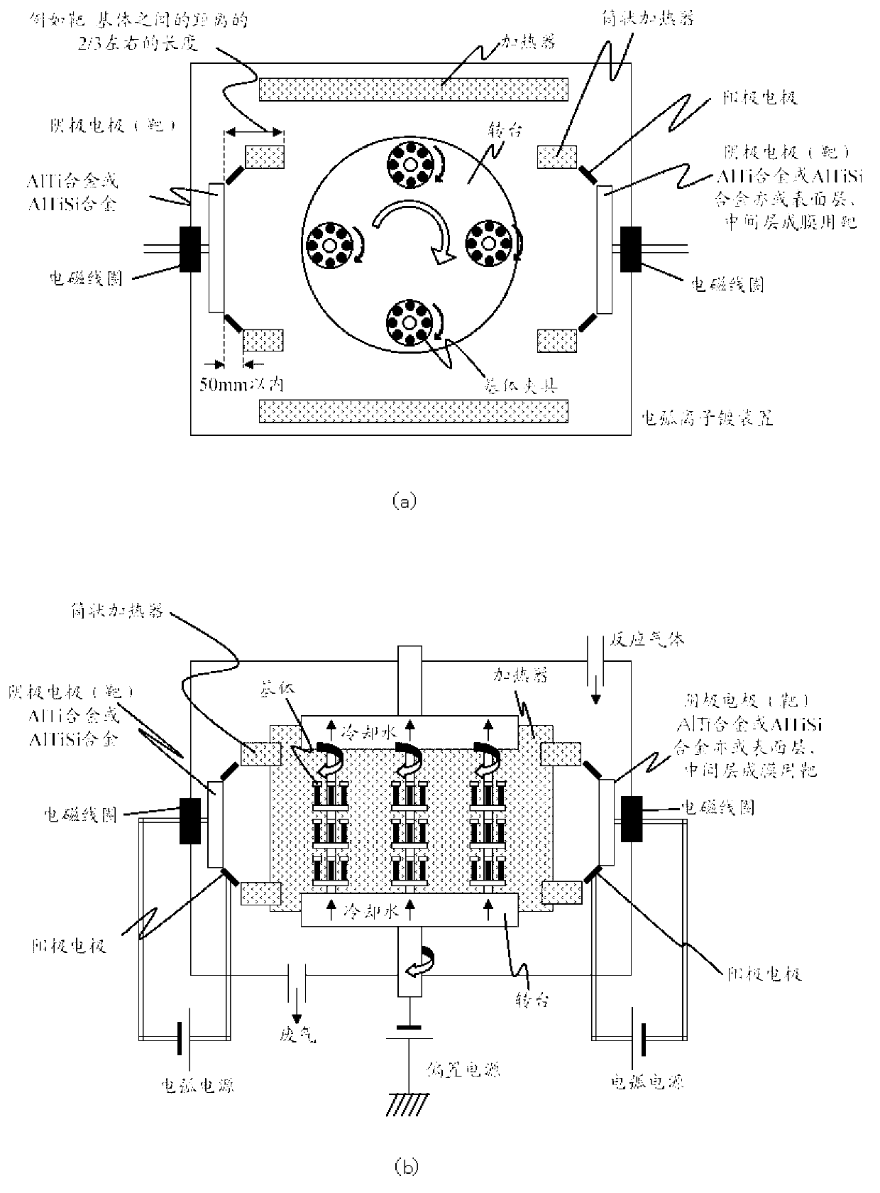
[0053] Next, put these tool bases A~E into figure 1 The arc ion plating device shown in the table performs Ti bombardment under the conditions shown in Table 2, and then, using the same target composition shown in Table 2...


PUM

PropertyMeasurementUnit
Long trailaaaaaaaaaa
Vickers hardnessaaaaaaaaaa

Abstract

Provided is a surface coating cutting tool with superior defect resistance and abrasion resistance. A surface coating cutting tool having a hard coating layer coated and formed on the surface of a tool substrate by means of a physical vapor deposition method, wherein the hard coating layer is formed of a compound carbonitride layer or a compound nitride layer with an average layer thickness of 0.5 to 8.0 [mu]m expressed by the compositional formula (Al1-x-yTixSiy)(N1-zCz), the hard coating layer contains metallic particles with an average sectional major axis of 0.05 to 0.5 [mu]m in which 90 at% or more of the constituent elements are metallic elements, the metallic particles are dispersed and distributed in the hard coating layer at a longitudinal section area ratio of 3 to 18 %, the constituent elements contain Al of 50 at% or more among the metallic particles, and when the longitudinal sectional area ratio of a particle satisfying conditions such as the aspect ratio of the longitudinal sectional shape being 2.0 or more and the acute angle formed between the sectional major axis and the substrate surface being 45 DEG or less is taken as A%, and when the longitudinal sectional area ratio of another particle is taken as B%, 0.3<=A/(A+B).

Description

technical field [0001] The present invention relates to a surface-coated cutting tool (hereinafter referred to as a coated tool), which is used, for example, by improving the fracture resistance of a hard coating layer in front milling of materials to be cut such as carbon steel and alloy tool steel. It exhibits excellent wear resistance even after long-term use. Background technique [0002] Conventionally, there is known, for example, a surface-coated cutting tool as disclosed in Patent Document 1, in which crystal grains of a compound grown from a droplet having a hard coating layer protrude from the surface of the film, and the crystal grains of the compound are When the length of the grain in the longitudinal direction is h (μm) and the layer thickness of the hard coating layer is T (μm), the melted Large columnar crystals starting from droplets grow and compressive stress is reduced to achieve a thicker film without impairing adhesion. [0003] In addition, there is ...

Claims


Application Information

Patent Timeline
IPC IPC(8): B23C5/16B23B27/14C23C14/06
CPCC23C14/0664B23C5/16B23B27/14
Inventor 佐藤峻仙北屋和明田中耕一田中裕介
Owner MITSUBISHI MATERIALS CORP
Why Eureka
Try Eureka