Temperature gradient liquid-liquid-liquid microextraction method

A temperature gradient and extraction technology, applied in liquid solution solvent extraction and other directions, can solve the problems of long extraction time and low absolute recovery rate, and achieve the effects of improving extraction recovery rate, simple operation and improving extraction efficiency.

Active Publication Date: 2013-06-05
重庆南派克仪表科技有限公司
View PDF3 Cites 3 Cited by
  • Summary
  • Abstract
  • Description
  • Claims
  • Application Information

AI Technical Summary

Problems solved by technology

[0003] Although liquid-liquid-liquid microextraction has many advantages, it has disadvantages such as long extraction time and low absolute recovery.

Method used


Image

  • Temperature gradient liquid-liquid-liquid microextraction method
  • Temperature gradient liquid-liquid-liquid microextraction method
  • Temperature gradient liquid-liquid-liquid microextraction method

Examples


Embodiment 1

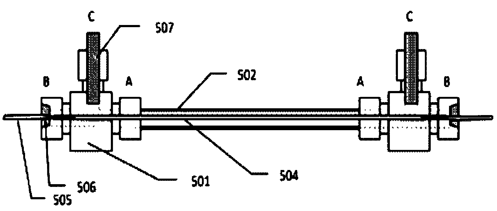
[0030] Embodiment 1: with figure 1 The extraction device shown realizes the extraction and enrichment of gibberellin GA3 in water

[0031] 1) Extraction device: This device is connected by a tee and a thin tube to form a shell-and-tube channel. Cut the polyvinylidene fluoride hollow fiber membrane that has been ultrasonically dried with acetone into 9 cm sections (the inner diameter of the membrane is 800 μm, the wall thickness is 200 μm, and the pore size is 0.2 μm). The coaxial structure is realized by the nesting of the inner tube and the outer tube. The inner tube is a hollow fiber membrane, and the outer tube is made of metal, inorganic material or polymer material, with a diameter of 1.3mm. The two ends of the outer tube are connected and sealed with the tee, and the hollow fiber membrane passes through the inner channel of the tee. lead out at one end. The receiving phase is imported and exported from the C terminals of the two tees.

[0032] 2) Provide phase confi...

Embodiment 2

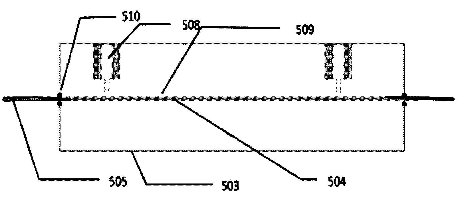
[0038] Embodiment 2: with figure 2 The extraction device shown realizes the extraction and enrichment of gibberellins GA1, GA3, and GA4 in water

[0039] 1) Extraction device: This device processes a shell-and-tube channel from a single piece of material. Cut the polypropylene hollow fiber membrane that has been ultrasonically dried with acetone into 9 cm sections (the inner diameter of the membrane is 600 μm, the wall thickness is 200 μm, and the pore diameter is 0.2 μm), and the dried membrane is passed through the AB end of the 1.05 mm diameter channel processed by PMMA material , and the gap between the AB end of the channel and the hollow fiber membrane is sealed with epoxy glue, and the two ends of the hollow fiber membrane are respectively connected with a stainless steel tube with an outer diameter of 0.6 mm and heated and sealed.

[0040] 2) Provide phase configuration: Dissolve GA1, GA3, and GA4 mixed standard samples in acetonitrile to obtain a 100 μg / mL stock sol...


PUM


Abstract

The invention relates to a temperature gradient liquid-liquid-liquid microextraction method. The temperature gradient refers to that a temperature difference exists between a receiving phase and a supplying phase (sample) of the liquid-liquid-liquid microextraction, wherein the receiving phase is a hot end and the supplying phase is a cold end. The site of the liquid-liquid-liquid microextraction is a coaxial tube-shell-type channel. Liquid layer segregation is supplied by a hollow fiber pipe, wherein the lateral wall of the fiber pipe is provided with micropores or is free from pores. Liquid which is neither immiscible with the liquid of the supplying phase nor the receiving phase is arranged on the surface of the hollow fiber pipe in a loaded mode. An outer shell body is sleeved outside the hollow fiber pipe, wherein the inner diameter of the outer shell body is larger than the outer diameter of the hollow fiber pipe. The supplying phase passes through the interior of the hollow fiber pipe, and the receiving phase is filled in a cavity between the hollow fiber pipe and the outer shell body. The outer shell body is heated so that the receiving phase is heated, thus the temperature gradient between the receiving phase and the supplying phase is achieved and used as mass transfer power, and an extraction recovery rate is improved.

Description

technical field [0001] The invention relates to a liquid-liquid-liquid micro-extraction method. Specifically, it relates to a liquid-liquid-liquid microextraction method in which there is a temperature gradient between a supply phase and a receiving phase. The micro-extraction device can be applied to the selective concentration and enrichment of various heat-stable compounds in complex samples. Background technique [0002] Since Pawliszyn (Analytical Chemistry 62 2145 (1990)) began to study solid-phase microextraction in 1990, microextraction technology has been widely used in analytical chemistry, mainly for the pretreatment of complex samples, with high enrichment factor and simple operation And features such as green environmental protection. In 1996, Dasgupta (Analytical Chemistry 68 1817 (1996)) and Cantwell (Analytical Chemistry 68, 2236. (1996)) introduced microextraction technology into liquid phase extraction. At first they used the form of single drop liquid ph...

Claims


Application Information

Patent Timeline
Patent Type & Authority Applications(China)
IPC IPC(8): B01D11/04
Inventor 关亚风吴倩沈铮陈亮吴大朋
Owner 重庆南派克仪表科技有限公司
Why Eureka
Try Eureka