Surface-coated cutting tool in which hard coating layer demonstrates excellent chipping resistance

A cutting tool and surface coating technology, which is applied in the field of surface coating cutting tools, can solve the problems of high temperature strength, toughness, adhesion can not be said to be sufficient, cutting edge chipping, etc.

Active Publication Date: 2013-06-05
MITSUBISHI MATERIALS CORP
View PDF8 Cites 4 Cited by
  • Summary
  • Abstract
  • Description
  • Claims
  • Application Information

AI Technical Summary

Problems solved by technology

In addition, from the viewpoint of prolonging the life of the tool, thickening of the hard coating layer is also required. However, the current situation is as follows: for example, the hard coating layer (for example, Al in the upper layer 2 o 3 When thickening the film, in the above-mentioned conventional coated tools, it is especially used for high-speed intermittent cutting under severe cutting conditions, that is, accompanied by high heat generation, and repeated and intermittent at extremely short pitches, When an impact load acts on the cutting edge during high-speed interrupted cutting, due to the Al in the upper layer 2 o 3 The high-temperature strength, toughness, and adhesion of the layer cannot be said to be sufficient, so it is easy to cause chipping on the cutting edge. For this reason, the service life is reached in a short time

Method used


Image

  • Surface-coated cutting tool in which hard coating layer demonstrates excellent chipping resistance
  • Surface-coated cutting tool in which hard coating layer demonstrates excellent chipping resistance
  • Surface-coated cutting tool in which hard coating layer demonstrates excellent chipping resistance

Examples


Embodiment

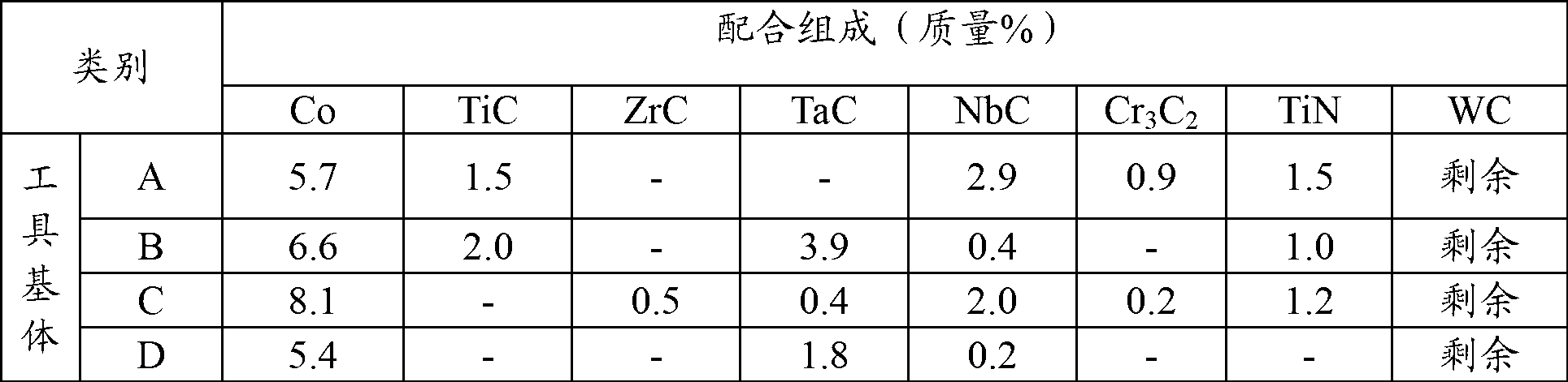
[0061] Prepare WC powder, TiC powder, ZrC powder, TaC powder, NbC powder, Cr 3 C 2 Powder, TiN powder and Co powder are used as raw material powders. These raw material powders are mixed into the compounding composition shown in Table 1, then wax is added and ball milled in acetone for 24 hours, and dried under reduced pressure. The green compact of the specified shape is vacuum sintered in a vacuum of 5 Pa and kept at a specified temperature in the range of 1370-1470 °C for 1 hour. Grinding, thereby manufacturing WC-based cemented carbide tool substrates A to D each having an insert shape specified in ISO·CNMG120408.

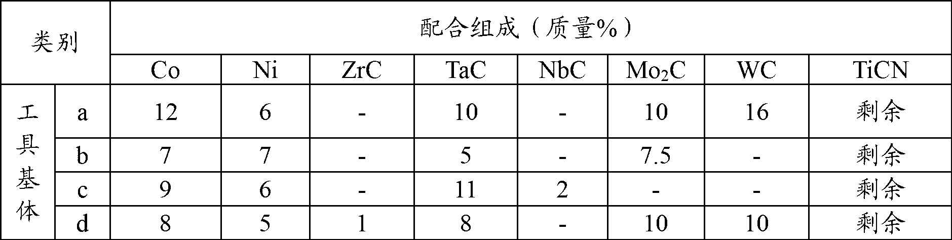
[0062] In addition, TiCN (mass ratio TiC / TiN=50 / 50) powder, Mo 2 C powder, ZrC powder, NbC powder, TaC powder, WC powder, Co powder, and Ni powder are used as raw material powders. These raw material powders are mixed into the compounding composition shown in Table 2. After wet mixing with a ball mill for 24 hours and drying, the The press-stamped compact is...


PUM

PropertyMeasurementUnit
The average particle sizeaaaaaaaaaa

Abstract

The present invention provides a surface-coated cutting tool in which a hard coating layer demonstrates excellent chipping resistance in high-speed intermittent machining. According to the surface-coated cutting tool provided by the invention, the surface of the tool substrate is coated by a lower layer composed of a Ti compound layer and an upper layer composed of an Al2O3 layer, wherein the Al2O3 layer consists of three regions, i.e., a lower region, a middle region and an upper region; and for each region, if a field-emission scanning electron microscope and an electronic back scattering diffraction image device are used for calculating the normal tilt angle distribution of a plane (0001) within a range of 0-90 degrees, the sum total degrees of the lower region accounts for a ratio of more than 60% within the range of 80-90 degrees, the sum total degrees of the middle region accounts for a ratio of more than 60% within the range of 70-80 degrees, and the sum total degrees of the upper region accounts for a ratio of more than 60% within the range of 0-10 degrees.

Description

technical field [0001] This invention relates to a surface-coated cutting tool (hereinafter referred to as coated cutting tool) in which a hard coating exhibits excellent chipping resistance in high-speed interrupted cutting with high heat generation and impact load acting on the cutting edge. tool). Background technique [0002] In the past, it is known that the surface of a tungsten carbide (hereinafter represented by WC)-based cemented carbide or titanium carbonitride (hereinafter represented by TiCN)-based cermet (hereinafter these are collectively referred to as tool substrates) formed on the surface of A coated tool made of a hard coating composed of the following (a) and (b): [0003] (a) The lower layer is a Ti compound layer, which is a Ti carbide (hereinafter referred to as TiC) layer, nitride (hereinafter also referred to as TiN) layer, carbonitride (hereinafter referred to as TiCN) layer, and carbonitride (hereinafter referred to as TiCN) layer formed by homoche...

Claims


Application Information

Patent Timeline
IPC IPC(8): B23B27/14C23C16/30
Inventor 奥出正树五十岚诚长田晃
Owner MITSUBISHI MATERIALS CORP
Why Eureka
Try Eureka