Closely attached type light emitting diode induction fluorescence detector for exciting light path

A technology of light-emitting diodes and induced fluorescence, which is applied in the field of fluorescence detectors, can solve the problems of increased optical distance, high cost, and complex structure of optical fibers, and achieve the effect of reducing optical distance and strong practicability

Active Publication Date: 2013-06-05
DALIAN INST OF CHEM PHYSICS CHINESE ACAD OF SCI
View PDF5 Cites 20 Cited by
  • Summary
  • Abstract
  • Description
  • Claims
  • Application Information

AI Technical Summary

Problems solved by technology

But only the LED beam within its aperture angle can be transmitted by it, and the use of optical fiber increases the optical distance
These two factors cause the light intensity in the detection area to be greatly weakened
Recently, it has been reported in the literature that LED-induced fluorescence detectors using both lens systems and optical fibers have achieved high sensitivity (10-10M), but their structures are too complicated and costly

Method used


Image

  • Closely attached type light emitting diode induction fluorescence detector for exciting light path
  • Closely attached type light emitting diode induction fluorescence detector for exciting light path

Examples


Embodiment 1

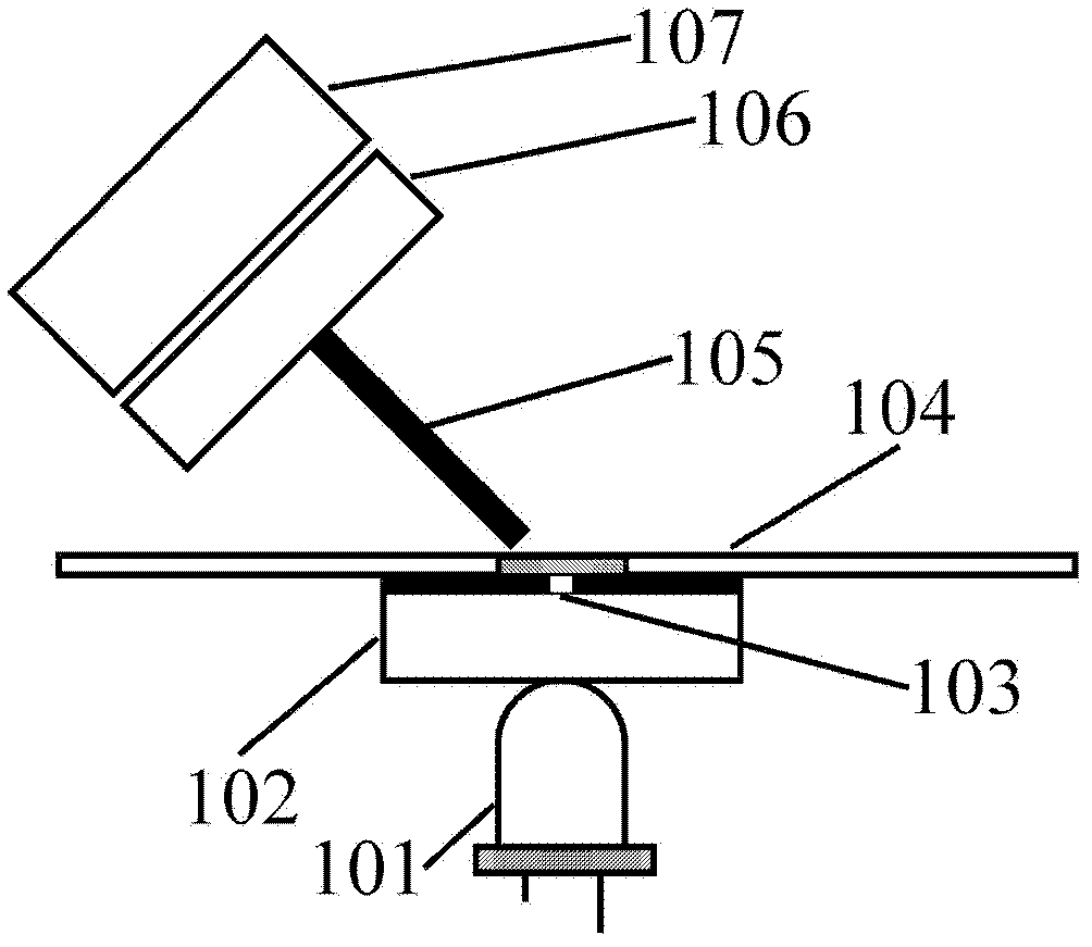
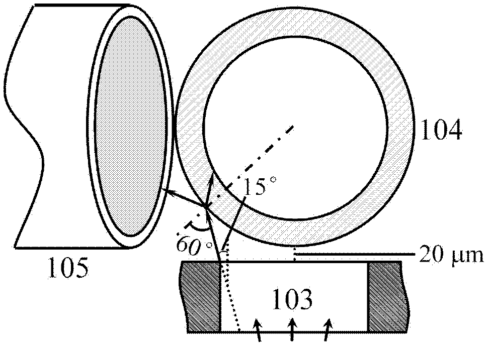
[0026] Such as figure 1 As shown, a light-emitting diode-induced fluorescence detector close to the excitation light path, its structure includes an excitation light source 101 (light-emitting diode), an excitation filter 102, a beam-limiting aperture 103, a capillary flow cell 104, and a receiving optical fiber 105, Emission filter 106 and photoelectric conversion device 107 (photomultiplier tube). Wherein, excitation light source 101 (light emitting diode), excitation filter 102, beam limiting aperture 103, and quartz capillary flow cell 104 whose outer wall is coated with polyimide are closely attached to each other. The excitation light path is perpendicular to the plane where the capillary flow cell and the receiving optical fiber are located. The generated signal is received by the receiving optical fiber 105, filtered by the emission filter 106, and then transmitted to the photoelectric conversion device 107 (photomultiplier tube) for detection.

[0027] The light so...


PUM

PropertyMeasurementUnit
thicknessaaaaaaaaaa
thicknessaaaaaaaaaa
transmittivityaaaaaaaaaa

Abstract

The invention relates to a light emitting diode induction fluorescence detector. According to the detector, a light emitting diode is adopted as an exciting light source, exciting light is filtered by an exciting light filter, and light beams are limited by small holes. After the light beams are limited, the exciting light is transferred to a capillary tube flow cell. A receiving optical fiber receives fluorescent light, and the fluorescent light is transferred to a photovoltaic conversion device to be detected after passing through an emission light filter. The light emitting diode, the light filters, the small holes and outer walls of an outer protective coating (such as polyimide) of the capillary tube flow cell are closely attached, and no condensing lens or exciting optical fibers are needed. The detector is compact in structure, convenient to use and low in cost. The fluorescent light can be received with high efficiency, the signal to noise ratio is improved and sensitivity of detection can be improved by optimizing the size of a divergence angle and the sizes of the small holes. The detector can be used for directly detecting fluorescent substances in a capillary tube running system, and can be used for detecting non-fluorescent substances when combined with a fluorescence indicator.

Description

technical field [0001] The invention relates to a light emitting diode induced fluorescence detector. Specifically relates to a fluorescence detector, which can directly detect fluorescent substances, and can also be combined with fluorescent markers to indirectly detect non-fluorescent substances. Background technique [0002] As a photoluminescent detection technology, fluorescence detection has the advantages of high sensitivity and strong selectivity, and is widely used in the detection of trace samples. Light-emitting diodes (LEDs) have the following advantages: long life, high stability, small size, low power consumption, low cost, and wide spectral coverage (from deep ultraviolet to near infrared), and have been applied to fluorescence detection. However, due to the nature of the LED itself as a surface light source and an incoherent light source, the light it emits has a large divergence angle, and it is difficult to converge the light spot to a size similar to the ...

Claims


Application Information

Patent Timeline
Patent Type & Authority Applications(China)
IPC IPC(8): G01N21/64
Inventor 关亚风耿旭辉吴大朋
Owner DALIAN INST OF CHEM PHYSICS CHINESE ACAD OF SCI
Why Eureka
Try Eureka