Novel desulfurization-denitrification integrated device

A denitrification and desulfurization chamber technology, applied in chemical instruments and methods, chemical/physical processes, physical/chemical process catalysts, etc., can solve problems such as easy breakage, waste of resources, and expensive catalysts

Inactive Publication Date: 2013-06-19
JIANGSU DONGDA THERMAL ENERGY MACHINERY MFG
View PDF4 Cites 6 Cited by
  • Summary
  • Abstract
  • Description
  • Claims
  • Application Information

AI Technical Summary

Problems solved by technology

The wet method includes lime-gypsum method, seawater method, ammonia method, double alkali method, etc. according to the different components of the absorption liquid. One or more of the shape and follicular shape, the specific surface area formed by the unit volume of liquid in the form of film and droplet absorption liquid is small, and the specific surface area formed by the unit volume of liquid in the form of bubbly absorption liquid is large, but the surface tension poor, easily broken
Flue gas denitrification technologies mainly include selective non-catalytic reduction (SNCR), selective catalytic reduction (SCR), activated carbon combined desulfurization and denitrification, etc. Among them, SCR technology has high denitrification efficiency and is widely used, but the catalyst is expensive and difficult to operate. high cost
The combined desulfurization and denitrification technology that has been developed and applied is also a combined process of flue gas desulfurization technology and flue gas denitrification technology. There are many problems such as waste of resources, large one-time investment, high operating cost, and difficulty in coordinating independent subsystems.

Method used


Image

  • Novel desulfurization-denitrification integrated device

Examples


Embodiment Construction

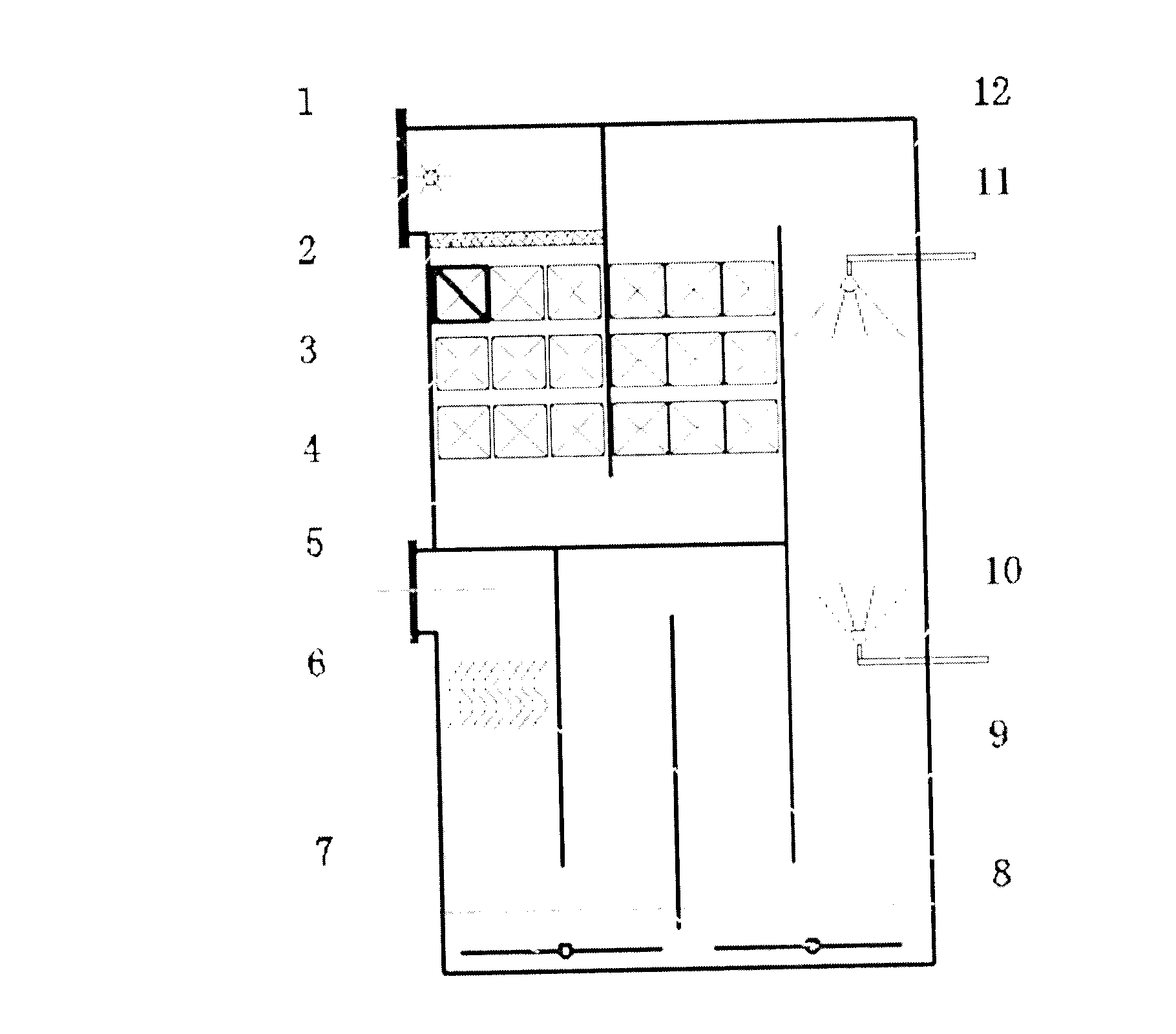
[0008] See attached figure 1 , the present invention includes: flue gas inlet 1, ammonia wind mixing spray gun 2, uniform flow splitter 3, catalyst module 4, denitrification chamber 5, flue gas outlet 6, follicle generator 7, demister 8, follicle desulfurization chamber 9. The secondary humidification nozzle 10, the primary humidification nozzle 11, and the tower body 12.

[0009] The flue gas enters the tower body 12 through the flue gas inlet 1, mixes with the ammonia gas injected by the ammonia-wind mixing spray gun 2, and is evenly dispersed in the denitration chamber 5 by the uniform distributor 3, and fully contacts with the catalyst module 4. The catalyst module is Attapulgite is used as the denitration catalyst carrier, and metal oxides such as vanadium oxide and tungsten oxide are used as catalysts. The nitrogen oxides in the flue gas undergo a catalytic reduction reaction with ammonia under the action of the catalyst, and the nitrogen oxides are reduced to nitrogen. ...


PUM


Abstract

The invention relates to a desulfurization-denitrification device for flue gas, and particularly relates to a desulfurization-denitrification integrated device using attapulgite as a denitrification catalyst support, and used for filter-bubble-absorbing type wet desulphurization. The device comprises a flue gas inlet, an ammonia-wind mixed spray gun, a uniform distribution flow divider, a catalyst module, a denitrification chamber, a flue gas outlet, a filter-bubble generator, a demister, a filter-bubble desulfurization chamber, a humidifying nozzle I, a humidifying nozzle II, a tower body, and the like. Flue gas enters in the tower body, and nitric oxides in the flue gas perform a catalytic reduction reaction under the action of a catalyst, so as to be reduced into nitrogen; and the denitrified flue gas enters in the filter-bubble desulfurization chamber from the denitrification chamber, sulfur dioxide in the flue gas is contacted with a desulfurizing agent in the filter bubbles generated by the filter-bubble generator and performs an acid-base neutralization reaction, so as to be desulfurized, and the flue gas obtained after water vapour in the flue gas is separated by the demister enters in a chimney via the flue gas, so as to be discharged, thus realizing desulfurization and denitrification on flue gas in the same device. The device can be widely used for desulfurization and denitrification for flue gas.

Description

technical field [0001] The invention relates to a flue gas desulfurization and denitrification device, in particular to an integrated desulfurization and denitrification device using attapulgite as a denitrification catalyst carrier and follicle absorption wet desulfurization. Background technique [0002] The flue gas discharged from the boiler (furnace) contains sulfur dioxide and nitrogen oxides, which cause very serious air pollution and acid rain, and cause huge economic losses. There are many methods for flue gas desulfurization and denitrification, and desulfurization technologies include dry, semi-dry and wet methods. Because the wet process is mature and efficient, the current desulfurization technology is mainly based on the wet process. The wet method includes lime-gypsum method, seawater method, ammonia method, double alkali method, etc. according to the different components of the absorption liquid. One or more of the shape and follicular shape, the specific s...

Claims


Application Information

Patent Timeline
Patent Type & Authority Applications(China)
IPC IPC(8): B01D53/75B01D53/90B01D53/78B01D53/50B01D53/56B01J23/30
Inventor 朱复东贾树山纪正飚熊梅林陈桂太
Owner JIANGSU DONGDA THERMAL ENERGY MACHINERY MFG
Why Eureka
Try Eureka