
Flue gas denitrification flow field simulation system and method

A technology of simulation system and simulation method, which is applied in the field of simulation system of flue gas denitrification flow field, can solve problems such as difficult to obtain stable and precise control of gas flow, low degree of automation of ash conveying and powder feeding devices, and pollution of the surrounding environment of the test site, etc. , to achieve the effect of improving test accuracy, test efficiency and maintaining goodness

Active Publication Date: 2013-06-19
FUJIAN LONGKING
View PDF4 Cites 6 Cited by
  • Summary
  • Abstract
  • Description
  • Claims
  • Application Information

AI Technical Summary

Problems solved by technology

[0008] First of all, the automation degree of the ash conveying and powder feeding device in the system is low, the accuracy of its weighing and powder feeding is low, and the concentration of fly ash is difficult to control;
[0009] Secondly, most of the induced draft fans of the system are small centrifugal fans, and the air volume of the system is adjusted by adjusting the opening of the damper. Factors such as test voltage fluctuations make it difficult to control the air flow stably and accurately;
[0010] Thirdly, during the ash deposition test, the fly ash is directly discharged from the outlet of the system, polluting the surrounding environment of the test site;
[0011] Finally, the induced draft fan of the system will generate a lot of noise pollution during the working process

Method used


Image

  • Flue gas denitrification flow field simulation system and method
  • Flue gas denitrification flow field simulation system and method
  • Flue gas denitrification flow field simulation system and method

Examples


Embodiment Construction

[0041] The core of the present invention is to provide a simulation system of flue gas denitrification flow field and a simulation method using the simulation system, which can reduce pollution and maintain the goodness of the surrounding environment of the test site.

[0042] In order to enable those skilled in the art to better understand the solution of the present invention, the present invention will be further described in detail below in conjunction with the accompanying drawings and specific embodiments.

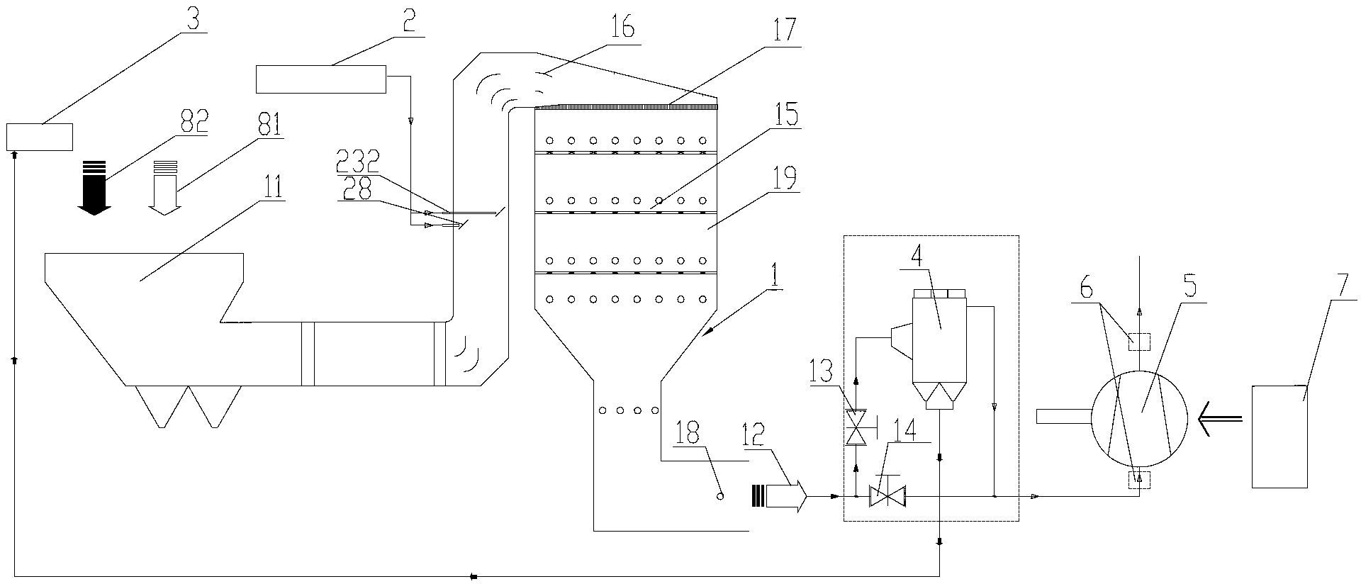
[0043] Please refer to figure 1 , figure 1 It is a schematic structural diagram of a simulation system provided by the present invention in a specific implementation manner.

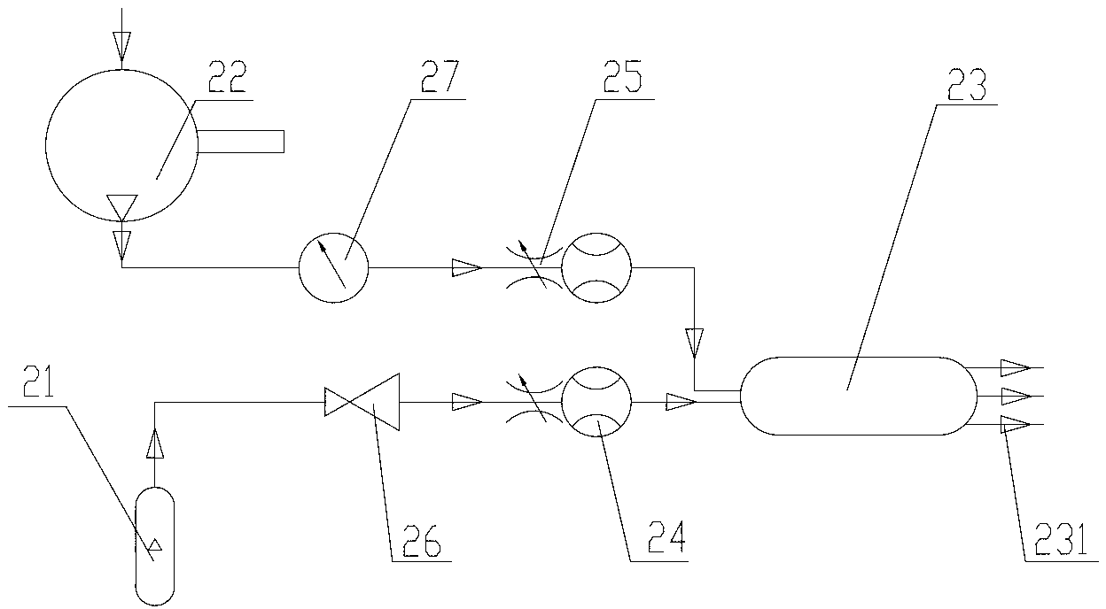
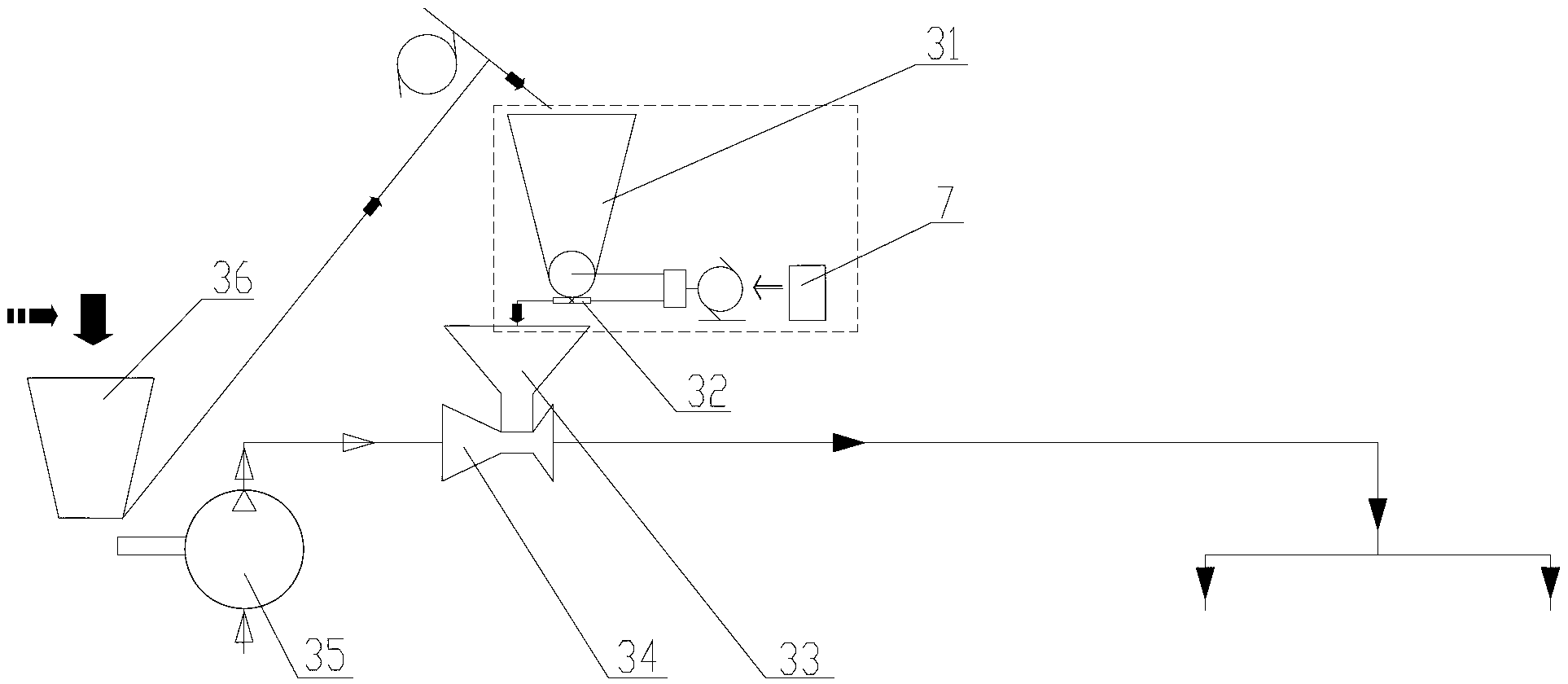
[0044] In a specific embodiment, the simulation system of the present invention includes a reactor 1, a tracer gas injection device 2 and a powder feeding device 3; the reactor 1 is used to complete the simulated denitration treatment of flue gas, and has an inlet 11 and an outlet 12 The reacto...


PUM


Abstract

The invention provides a flue gas denitrification flow field simulation system and method which are environment-friendly. The simulation system comprises a reactor, a tracer gas jetting device and a powder throwing device, wherein the tracer gas jetting device is connected with a vertical flue of the reactor; the powder throwing device comprises a feeder and a measurement scale connected with an outlet of the feeder; the measurement scale is in signal connection with a control device of the simulation system; the powder throwing amount is stored in the control device; and the control device controls the measurement scale to weigh dust, with the same amount as the powder throwing amount, from the feeder, and the dust is input into an inlet of the reactor. The simulation method comprises the following steps: setting a testing mode; preparing simulated flue gas, weighing the dust with the same amount as the powder throwing amount, and mixing the dust with air with the corresponding amount to form the simulated flue gas if a dust deposition test is performed, and forming the simulated flue gas by employing air if tests except the dust deposition test are performed; and mixing the simulated flue gas with tracer gas for performing simulated denitrification, and removing the dust and discharging the dust.

Description

technical field [0001] The invention relates to the technical field of flue gas denitrification, in particular to a simulation system of flue gas denitrification flow field. The present invention also relates to a simulation method using the above simulation system. Background technique [0002] SCR (Selective Catalytic Reduction, Selective Catalytic Reduction) denitrification technology is currently the most widely used flue gas denitrification technology. Its denitrification mechanism is to convert the reducing agent NH 3 Spray into the flue gas, after uniform mixing, NH 3 Oxidation-reduction reaction occurs with NOx in flue gas under the action of catalyst, so that NOx is reduced to harmless N 2 and H 2 O. [0003] Since the flow field in the denitrification system and the mixing uniformity of flue gas and ammonia are the key factors affecting the efficiency of SCR denitrification, in order to make the SCR denitrification system operate efficiently, the velocity dist...

Claims


Application Information

Patent Timeline
Patent Type & Authority Applications(China)
IPC IPC(8): B01D53/90B01D53/56G01N33/00
Inventor 叶兴联杨丁苏寅彪李立锋余盈然刘栋栋张小龙
Owner FUJIAN LONGKING
Learn More