Laser processing equipment for thin-wall pipes

A thin-walled pipe and laser processing technology, which is applied in laser welding equipment, metal processing equipment, welding equipment, etc., can solve the problems of low processing accuracy and slow processing speed, and achieve high processing accuracy, fast processing speed and easy replacement Effect

Active Publication Date: 2013-07-24
KUNSHAN THETA MICRO
View PDF6 Cites 9 Cited by
  • Summary
  • Abstract
  • Description
  • Claims
  • Application Information

AI Technical Summary

Problems solved by technology

[0009] The purpose of the present invention is to at least solve one of the above-mentioned technical defects, especially to solve the pr

Method used


Image

  • Laser processing equipment for thin-wall pipes
  • Laser processing equipment for thin-wall pipes
  • Laser processing equipment for thin-wall pipes

Examples


Embodiment Construction

[0027] Embodiments of the present invention are described in detail below, examples of which are shown in the drawings, wherein the same or similar reference numerals designate the same or similar elements or elements having the same or similar functions throughout. The embodiments described below by referring to the figures are exemplary only for explaining the present invention and should not be construed as limiting the present invention.

[0028] In the description of the present invention, it should be understood that the orientation or positional relationship indicated by the terms "upper", "lower", "inside" and the like are based on the orientation or positional relationship shown in the drawings, and are only for the convenience of describing the present invention and simplified descriptions, rather than indicating or implying that the device or element referred to must have a specific orientation, be constructed and operate in a specific orientation, and thus should no...


PUM


Abstract

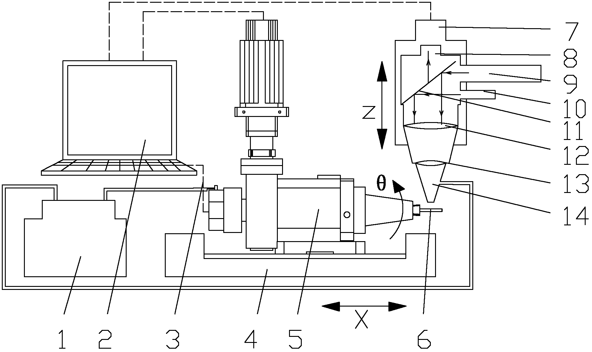
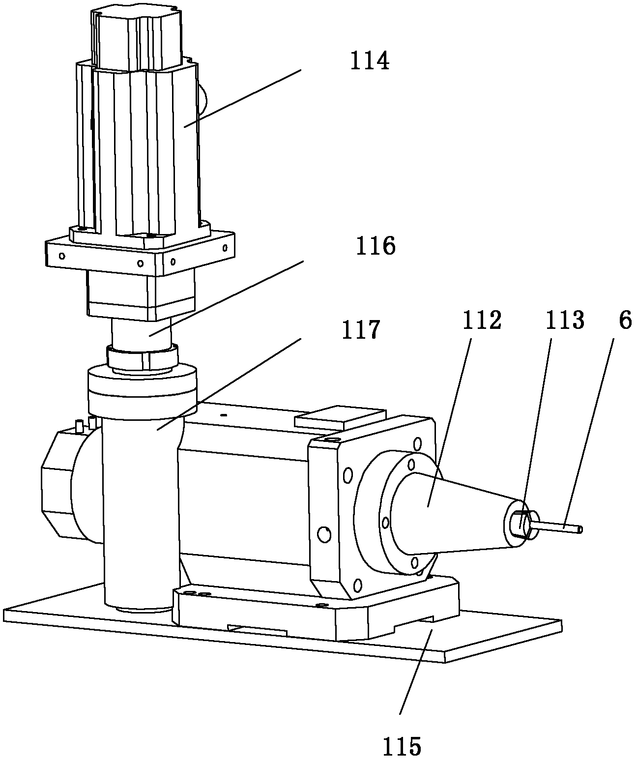
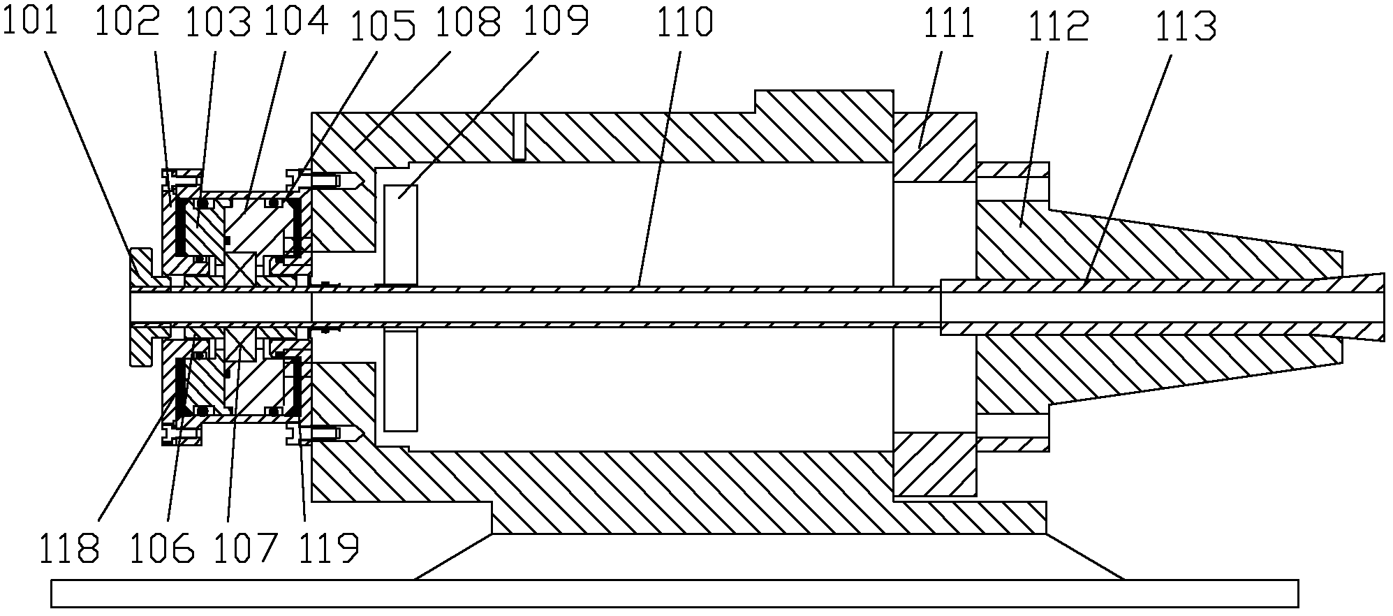
The invention provides laser processing equipment for thin-wall pipes, which comprises a rotary shaft, a linear shaft, a laser cutting head, an auxiliary high-pressure air-supplying unit, a Z axis module, a laser generator, a collimation and beam expanding lens, a lighting source, a 45-degree reflector, a CCD (Charge Coupled Device) and a control system. The laser cutting head comprises a laser nozzle, a protection lens and a focusing lens. The rotary shaft comprises a motor, a coupler, a worm, a worm gear, a pull-rod module, a shell, an end cover and a clamp head. The pull-rod module comprises a pull-rod cover, a piston, a pull-rod seat, a rolling bearing, a shaft sleeve and a hollow pull rod. The CCD is used for observing the focusing condition of optical spots during position adjusting of the laser optical spots, checking the processing condition anytime during the machining process, and videoing the whole machining process. The control system comprises a moving control unit fro controlling the linear shaft, the rotary shaft and the Z axis module, and a laser control unit for controlling the laser generator. The laser processing equipment for the thin-wall pipes disclosed by the invention is quick in processing speed and high in processing accuracy.

Description

[0001] technical field [0002] The invention belongs to the field of laser micromachining of thin-walled pipes, and relates to laser processing equipment, in particular to laser processing equipment for thin-walled pipes. [0003] Background technique [0004] Vascular stent refers to the placement of internal stents in the diseased segment on the basis of luminal balloon expansion to support the stenotic and occluded segment of the vessel, reduce the elastic retraction and reshaping of the vessel, and maintain the smooth blood flow in the lumen. The role of the scaffold is to keep the blood vessels open. Some internal stents can also prevent restenosis. Mainly divided into coronary stents, cerebrovascular stents, renal artery stents, aortic stents, etc. [0005] The processing of vascular stents in my country develops late, the technology is relatively backward, and there is a big gap in processing accuracy and quality compared with foreign countries. At present, most o...

Claims


Application Information

Patent Timeline
IPC IPC(8): B23K26/38B23K26/42B23K37/053B23K26/06B23K26/142
Inventor 魏志凌宁军夏发平马秀云
Owner KUNSHAN THETA MICRO
Why Eureka
Try Eureka