Method for dynamically monitoring health states of railway continuous-beam bridge and rail overlapping device

A health status and dynamic monitoring technology, applied in the direction of tracks, instruments, roads, etc., can solve problems such as measurement difficulties, strong electromagnetic field interference, and laser atmospheric influence, and achieve accurate measurement, strong anti-interference ability, and good long-term stability Effect

Inactive Publication Date: 2013-07-24
WUHAN UNIV OF TECH
View PDF6 Cites 37 Cited by
  • Summary
  • Abstract
  • Description
  • Claims
  • Application Information

AI Technical Summary

Problems solved by technology

Direct contact measurement uses the detector vibration pickup and acceleration sensor directly attached to the monitoring point to convert the mechanical movement into the required physical quantity. However, the electrical signal detector has zero drift after long-term continuous operation, which cannot be continuously monitored for a long time. There is a problem of strong electromagnetic field interference generated when heavy-duty electric locomotives pass by; electromagnetic radiation detection transmits electromagnetic waves, and then performs signal processing on the received target echoes to extract the vibration information of the target. The disadvantage is that it is easily affected by the electromagnetic waves of the surrounding environment. Interference and multipath reflection effects cannot effectively reflect the actual vibration state of the bridge girder
Laser interferometry uses optical measuring instruments and uses the Michelson interference principle for measurement. It has strong anti-interference ability and is not subject to electromagnetic and ground wave interference. However, the laser is greatly affected by the atmosphere, and it is difficult to measure in bad weather.

Method used


Image

  • Method for dynamically monitoring health states of railway continuous-beam bridge and rail overlapping device

Examples


Embodiment Construction

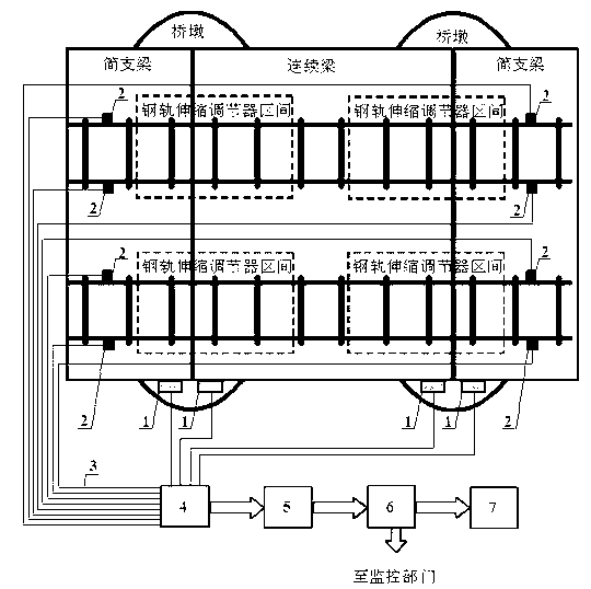
[0022] Such as figure 1 Shown, the railway continuous girder bridge of the present invention and the health status dynamic monitoring method of the rail expansion regulator. It uses 4 fiber grating vibration sensors to monitor the vibration amplitude and frequency of the continuous beam and simply supported beam of the bridge under the action of heavy dynamic load; 8 fiber grating displacement sensors Carry out rail crawling displacement monitoring; the system device includes 4 fiber grating vibration sensors 1 (including supporting sensor housing, fixing device, auxiliary device), 8 fiber grating displacement sensors 2 (including supporting sensor housing, fixing device, auxiliary device ), transmission optical fiber 3, optical fiber connection box 4, demodulator 5, data processing terminal 6, alarm device 7.

[0023] The fiber grating vibration sensor 1 is mainly made of fiber grating, vibrating mass, and cantilever structure package, wherein the fiber grating sensor is solid...


PUM


Abstract

The invention provides a method for dynamically monitoring health states of a railway continuous-beam bridge and a rail overlapping device. Four fiber bragg grating vibrating sensors are arranged on the beam body end parts of a continuous beam and a simply supported beam; eight fiber bragg grating displacement sensors are arranged on a seamless rail, connected with the rail overlapping device, at a bridge seam joint; the vibrating sensors are used for performing vibration monitoring on a bridge seam body; the displacement sensors are used for performing continuous monitoring on the crawling displacement of the rail; and signals monitored by all the sensors are transmitted to a fiber splice box by virtue of a transmission fiber so as to be gathered, then are output to a demodulator so as to be demodulated and finally are transmitted to a data processing terminal so as to be processed and displayed, so that on-line dynamic monitoring is realized; by virtue of performing contrastive analysis on the historical change trend of data features and monitoring the health states of the railway continuous-beam bridge and the rail overlapping device, alarming is started if an alarm threshold value is exceeded, and the result is uploaded to a monitoring department in real time. The method can be used for dynamically monitoring the vibration of the bridge beam body and the displacement change of the rail in an on-line manner, prewarning in time and ensuring the heavy-load safe operation of a railway bridge.

Description

technical field [0001] The invention belongs to the technical field of safety monitoring of heavy-duty railway bridges where optical fiber grating sensing technology is applied. The invention relates to a method for on-line, dynamic long-term monitoring and data comparison of the vibration amplitude and frequency of the girder body of a railway continuous girder bridge and the creeping displacement of a rail telescopic adjuster based on fiber grating sensing technology. Background technique [0002] The heavy-duty coal transportation line is the lifeline of the national economy. With the opening of the 10,000-ton and 20,000-ton heavy-duty trains on the coal transportation line, the safe operation of its lines, especially bridges, has attracted more and more attention. Because bridges need to cross rivers, valleys and roads, in order to increase the span, continuous beam structures are often used. Compared with the simply supported beam structure, under the action of the tra...

Claims


Application Information

Patent Timeline
Patent Type & Authority Applications(China)
IPC IPC(8): E01B35/12G01H9/00G01B11/02
Inventor 李维来刘捷许儒泉刘芳程健潘建军代鑫鲁晓珊庞锦
Owner WUHAN UNIV OF TECH
Why Eureka
Try Eureka