Method, device and system for radio wave refraction correction

A technology of radio wave refraction and refractive index, applied in the field of radio wave refraction correction method, device and system, can solve the problems of long calculation time, function limitation and high cost

Active Publication Date: 2013-07-24
THE 22ND RES INST OF CHINA ELECTRONICS TECH GROUP CORP
View PDF3 Cites 14 Cited by
  • Summary
  • Abstract
  • Description
  • Claims
  • Application Information

AI Technical Summary

Problems solved by technology

Both of these methods have the problems of high cost and complicated technology.
For example, occultation detection needs to cooperate with low-orbit satellite joint observation, and is restricted by occultation events; network tomography requires multiple receivers to be arranged in a certain area and in a certain configuration, which requires a good solution for communication between them and data transmission, and the calculation takes a long time
[0005] Based on the above analysis, the current tropospheric and ionospheric detection methods have disadvantages such as complex operations, high operating costs, low real-time performance, poor mobility, and limited continuous observation capabilities, which are not convenient for actual operation and application in engineering, which to a certain extent restricts The accuracy of navigation, positioning, measurement and control equipment, etc., greatly restricts its functions and becomes a "bottleneck" for improving equipment and system performance
Therefore, it is necessary to develop low-cost, portable, real-time and high-precision detection methods and equipment that are convenient for engineering applications, so as to make up for the shortcomings of the lack of radio wave environment perception in engineering in my country, and to improve and improve the performance of navigation, positioning, measurement and control equipment, etc. Lift to provide support

Method used


Image

  • Method, device and system for radio wave refraction correction
  • Method, device and system for radio wave refraction correction
  • Method, device and system for radio wave refraction correction

Examples


no. 1 example

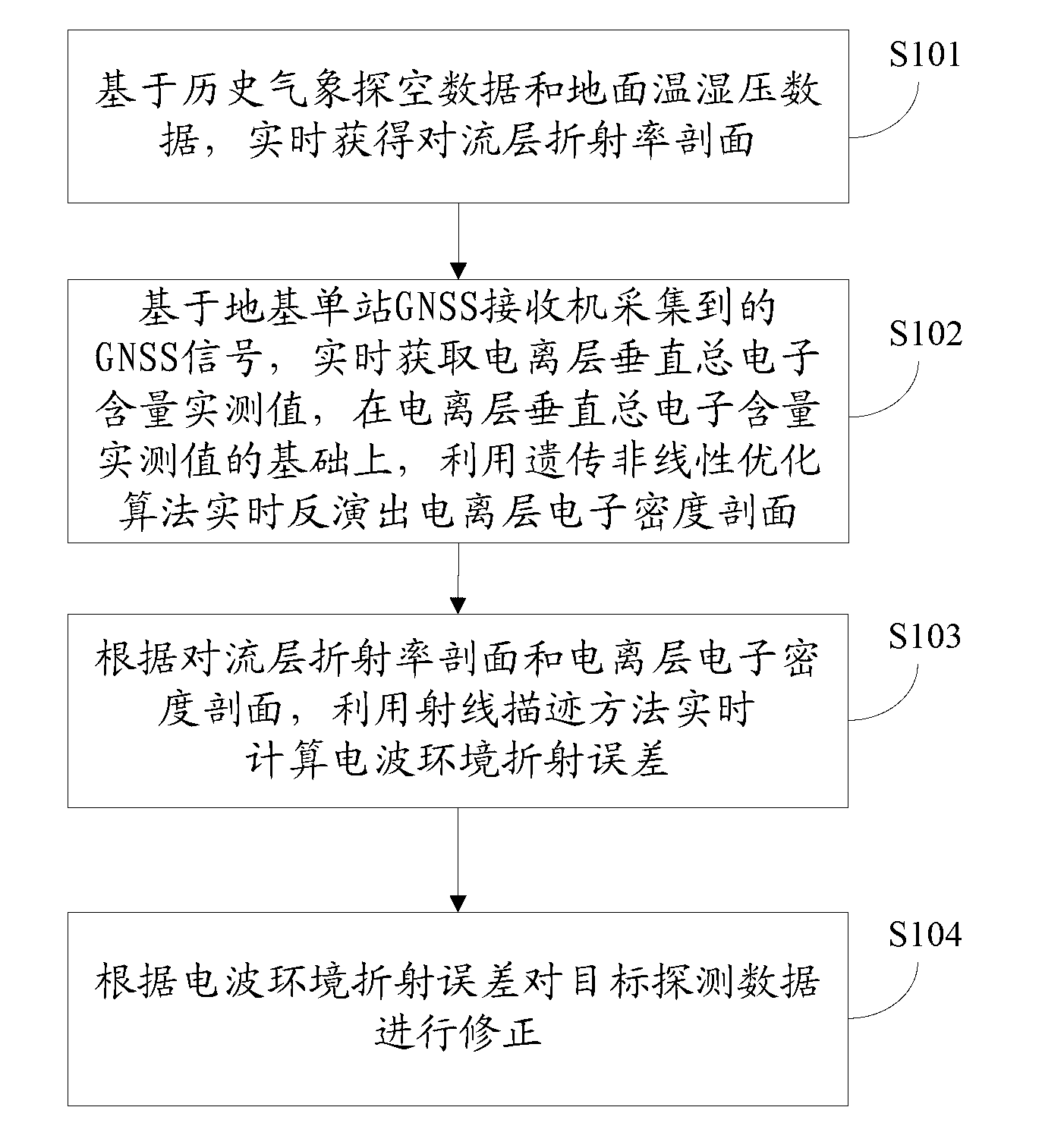
[0083] In the first embodiment of the present invention, a radio wave refraction correction method, such as figure 1 shown, including the following specific steps:

[0084] Step S101, based on historical meteorological sounding data and surface temperature and humidity pressure data, the tropospheric refractivity profile is obtained in real time.

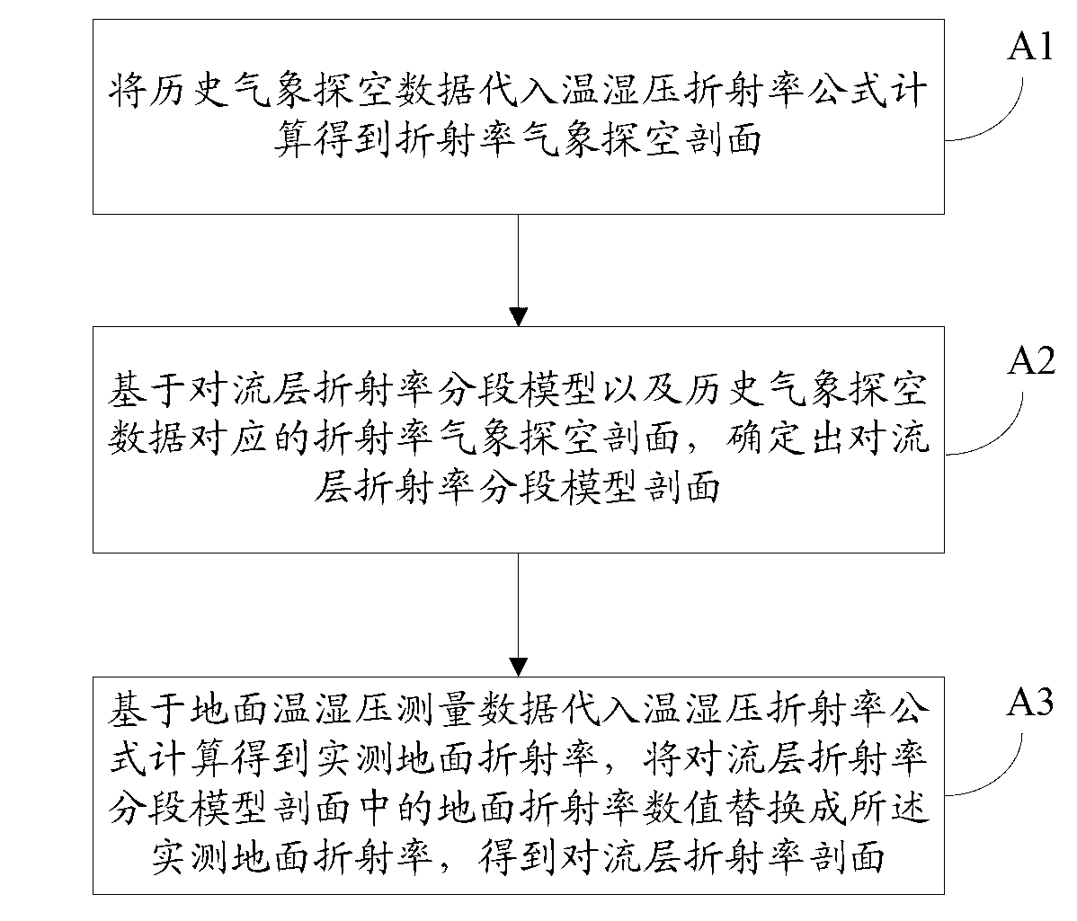
[0085] Specifically, such as figure 2 As shown, step S101 includes the following processes:

[0086] A1. Substituting the historical meteorological sounding data into the temperature and humidity pressure refractive index formula to calculate the refractivity meteorological sounding profile.

[0087] The tropospheric refractive index N′ can be expressed as a function of atmospheric state parameters (atmospheric pressure P, air temperature T, and water vapor pressure E), that is, the temperature and humidity pressure refractive index formula, as follows:

[0088] N ′ = 77....

no. 2 example

[0166] The second embodiment of the present invention is a device for implementing the radio wave refraction correction method described in the first embodiment, such as Figure 5 shown, including the following components:

[0167] The tropospheric data processing unit 100 is used to obtain the tropospheric refractivity profile in real time based on historical meteorological sounding data and ground temperature and humidity pressure data;

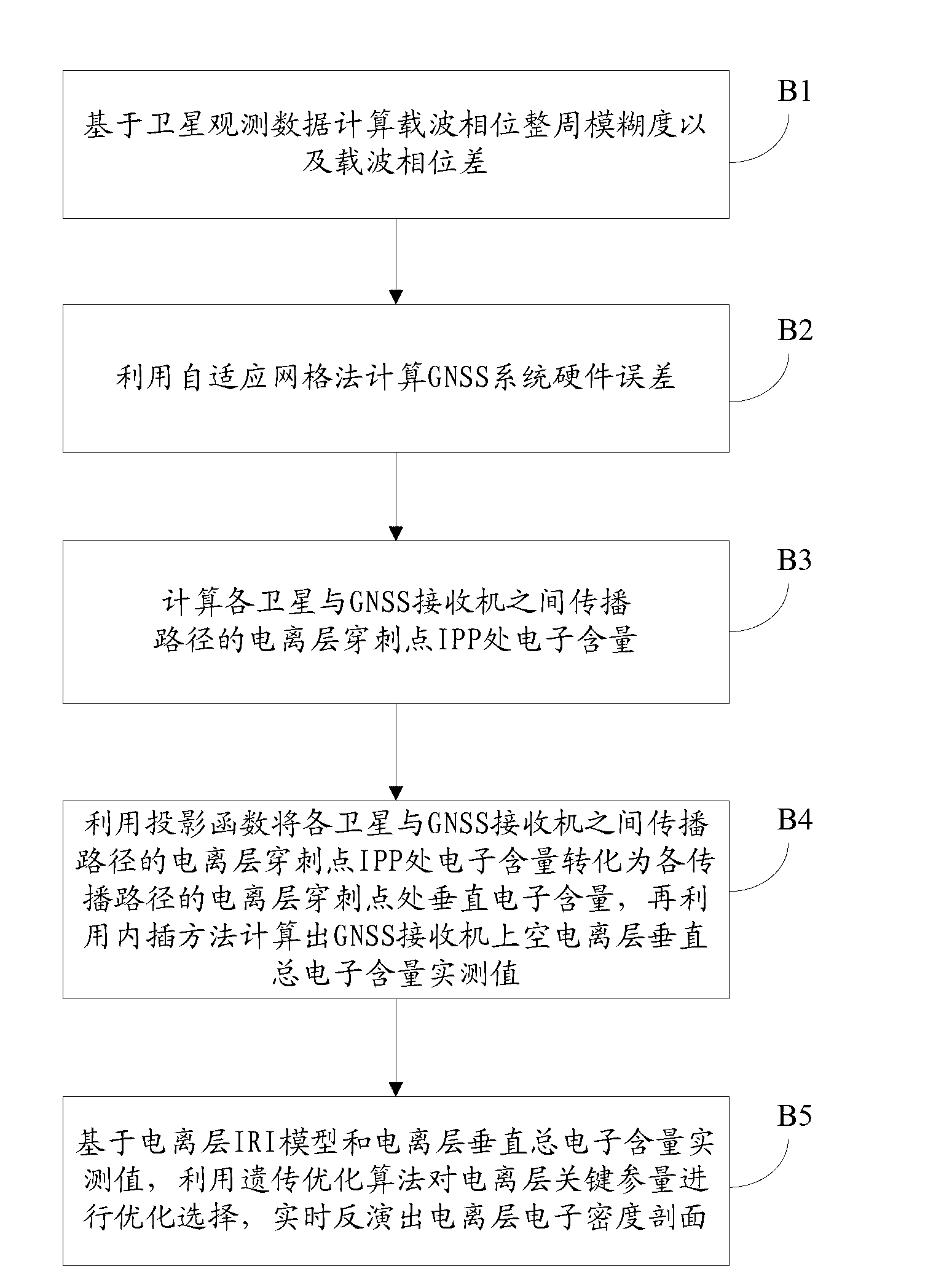
[0168] The ionospheric data processing unit 200 is used to obtain the measured value of the vertical total electron content of the ionosphere in real time based on the GNSS signal collected by the ground-based single-station GNSS receiver, and based on the measured value of the vertical total electron content of the ionosphere, use the genetic nonlinear The optimized algorithm inverts the ionospheric electron density profile in real time;

[0169] The refractive index error calculation unit 300 is used to calculate the radio wave environme...

no. 3 example

[0171] In the third embodiment of the present invention, a system for implementing the radio wave refraction correction method described in the first embodiment is located at the detection station. means of correction method), where,

[0172] 1. Data collection equipment, specifically comprising: a GNSS receiver for collecting GNSS signals, and a meteorological data collection unit for collecting temperature, humidity and pressure data; the meteorological data collection unit is fixedly connected to the GNSS receiver.

[0173] Further, such as Figure 6 , 7 As shown, the GNSS receiver includes: GNSS receiving antenna 501, antenna support 502 and GNSS satellite monitoring module 503 (the GNSS satellite monitoring module runs in the computer); Digital converter 506; Wherein, GNSS receiving antenna 501 is installed on the top of antenna support 502, GNSS receiving antenna 501 is connected with GNSS satellite monitoring module 503 by low-loss radio frequency line, GNSS satellite...


PUM


Abstract

The invention discloses a method, a device and a system for radio wave refraction correction. The method comprises the following steps of: based on historical meteorological sounding data and ground temperature-humidity-pressure data, obtaining troposphere refractive index profile in real time; based on a GNSS (Global Navigation Satellite System) signal acquired by a ground-based singular GNSS receiver, obtaining an ionized layer vertical total electron content measured value in real time, and based on the ionized layer vertical total electron content measured value, inversing the ionized layer electron density profile through a genetic non-linear optimization algorithm; calculating the radio wave environment refraction error through a ray tracing method according to the troposphere refractive index profile and the ionized layer electron density profile; and correcting the target detection data. The method, the device and the system can improve the radio wave environment sensory capability in engineering, accurately provide the radio wave environment refraction error and effectively improve the detection precision of a target.

Description

technical field [0001] The invention relates to the technical field of radio wave environment detection and radio application, in particular to a radio wave refraction correction method, device and system. Background technique [0002] Due to the existence of the radio wave environment, the refractive index of the atmosphere is different from the refractive index in the vacuum, and the signal has a refraction effect during the propagation process, which makes the speed and direction of the signal propagation change to a certain extent, resulting in a certain measurement deviation. In high-precision measurement and control systems such as aerospace measurement and control, radar detection, and navigation and positioning, it is necessary to correct the refraction error of the system measurement value to compensate for the error caused by the radio wave environment. The perception and detection of radio wave environment is the key to determine the accuracy of atmospheric refrac...

Claims


Application Information

Patent Timeline
IPC IPC(8): G01D3/028G01W1/02G01T1/29
CPCY02A90/10
Inventor 康士峰刘琨赵振维林乐科李建儒陈祥明朱庆林王红光孙方丁宗华
Owner THE 22ND RES INST OF CHINA ELECTRONICS TECH GROUP CORP
Why Eureka
Try Eureka