Photovoltaic power generation component junction box

A photovoltaic power generation and junction box technology, applied in photovoltaic power generation, photovoltaic modules, electrical components, etc., can solve the problems of strengthening the thermal interference of bypass diodes in solar junction boxes, permanent failure of devices, and unreasonable packaging forms, etc., to reduce Heat transfer interference effect, good electrical insulation performance, effect of reducing heat interference effect

Active Publication Date: 2013-07-31
山东中能技术有限公司
View PDF8 Cites 9 Cited by
  • Summary
  • Abstract
  • Description
  • Claims
  • Application Information

AI Technical Summary

Problems solved by technology

[0007] At this time, the bypass diode 1 is in forward conduction. Under the current of 10A, the Schottky bypass diode has a power of about 5W. Since the current junction box is a closed cavity, there is no air convection heat dissipation; the heat transfer path is: Bypass diode chip--bypass diode chip plastic package--air medium in the junction box cavity--junction box plastic shell--outside; the plastic is the poor heat conduction medium of the air in the junction box cavity, and the bypass diode has serious damage Overheating; a typical temperature rise test shows that: in the current packaging form of the bypass diode R6, the junction temperature of the bypass diode is 150-200°C, the ambient temperature of the air in the junction box is about 90-110°C, and the temperature of the junction box shell is about 90 ℃; the above data show that the heat generated by the bypass diode cannot be effectively dissipated, and the gradient between the junction temperature and the ambient temperature is greater than 50 ℃; it shows that the R6 package currently used is unreasonable; although the industry adopts better heat dissipation TO263/220 package form, but the current structure of the junction box determines that its improvement is still limited
[0008] The more serious problem is: solar modules are installed on the roof, outdoors, deserts or plateaus with good sunshine, it is entirely possible that the bypass diodes work in the bypass state for a long time during the power generation operation, this time may be 10 minutes, it may be 10 hours, maybe even a month or more, such as a flock of birds shitting on the solar modules, blocking the cells, it is extremely unlikely to be cleaned up in time; this will cause the bypass diode to work at 150-200°C all the time Under high temperature; working at high temperature for a long time, not only the service li

Method used


Image

  • Photovoltaic power generation component junction box
  • Photovoltaic power generation component junction box
  • Photovoltaic power generation component junction box

Examples


Embodiment 1

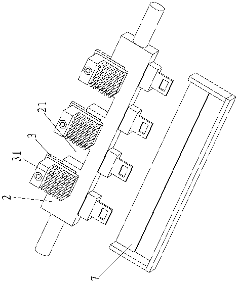
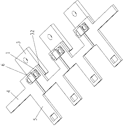
[0039] Embodiment 1: as Figure 1-2 As shown, a junction box for a photovoltaic power generation module includes a box body 7 on which a diode chipset and a package body 2 for packaging the diode chipset are arranged. The diode chipset has at least one bypass diode 1. In this implementation example Figure 1-2 There are three shown: the connecting terminal 4 electrically connected to the cable at both ends of the bypass circuit and the box body 7, the connecting terminal 5 of the busbar of the battery assembly electrically connected to each bypass diode 1, and the connecting terminal 5 of the busbar of adjacent battery assemblies A bypass diode chip jumper 6 is provided; the box body 7 shown in the figure is a partial diagram of the box body 7 .

[0040] A heat sink 3 for heat dissipation is provided under each bypass diode 1 , and the heat sink 3 and the bypass diode 1 are electrically insulated by a thermally conductive insulating sheet 32 ​​, and the heat sink 3 extends to...

Embodiment 2

[0045] Embodiment 2: as Figure 3-4 As shown, a junction box for a photovoltaic power generation module includes a box body 7 on which a diode chipset and a package body 2 for packaging the diode chipset are arranged. The diode chipset has at least one bypass diode 1. In this implementation example Figure 4 There are three shown; the bypass diode 1 at both ends of the box body 7 is also electrically connected to the cable lead terminal 4, and each bypass diode 1 and the cable lead terminal 4 are electrically connected to the battery assembly bus connection terminal 5, and the adjacent battery assembly A bypass diode chip jumper 6 is provided between the bus strip connection terminals 5 .

[0046] The diode chipset is fully encapsulated and packaged with electrically insulating and highly thermally conductive epoxy resin, and molded together with the package body 2 at one time.

[0047] At the same time, the bypass diodes 1 are respectively arranged on both sides of the pack...


PUM


Abstract

The invention relates to a photovoltaic power generation device, in particular to a photovoltaic power generation component junction box. The photovoltaic power generation component junction box adopts the following technical scheme that the photovoltaic power generation component junction box comprises a box body, a diode chip set provided with at least one bypass diode, a packaging body used for packaging the diode chip set, and radiating fins that are used for radiating the bypass diodes, are in electrical insulation with the bypass diodes, and extend out of the box body. According to the photovoltaic power generation component junction box, the heat of the bypass diodes is led out of the junction box, so that the radiating performance of the bypass diodes is improved, and the problem of temperature rise of the bypass diodes in the prior art is solved effectively.

Description

technical field [0001] The invention relates to a photovoltaic power generation device, in particular to a junction box of a photovoltaic power generation component. Background technique [0002] Since the beginning of the 21st century, the photovoltaic new energy industry represented by solar energy has achieved rapid development; in order to improve the reliability of the current solar power generation system and overcome the unavoidable "hot shift" effect of solar cell components, the industry adopts the method of It provides bypass protection, such as providing a bypass path for every 12-24 cells connected in series; when one or several cells are blocked for some reason, the bypass diode is in forward conduction, providing bypass The road path, so that the rest of the cells that are not covered can still work normally, and at the same time avoid the damage of the covered cells due to the thermal shift effect. [0003] Arizona State University Photovoltaic Testing Labora...

Claims


Application Information

Patent Timeline
IPC IPC(8): H01L31/048H01L23/367H02S40/34
CPCY02E10/50H01L23/36H01L2924/0002H02S40/345H01L2924/00
Inventor 冯春阳戴胜强高圣超
Owner 山东中能技术有限公司
Why Eureka
Try Eureka