OLED (organic light-emitting diode) coating machine with dual-rotation mechanism

A dual-rotor, coater technology used in the manufacture of OLEDs with larger dimensions. It can solve the problems that the coating uniformity of the sample substrate fails to meet the device requirements, is not suitable for OLED coating, and the thickness of the evaporated layer is uneven, and achieves the effect of improving the probability, increasing kinetic energy and improving the pass rate.

Inactive Publication Date: 2013-08-14
SOUTHEAST UNIV +1
View PDF4 Cites 5 Cited by
  • Summary
  • Abstract
  • Description
  • Claims
  • Application Information

AI Technical Summary

Problems solved by technology

At present, the evaporation of organic materials still has some disadvantages, such as low effective utilization rate (<10%), non-uniform dopant composition on the evaporation layer, uneven thickness of the evaporation layer, unstable evaporation rate, easy pollution of the vacuum chamber, etc. , resulting in the coating uniformity of the sample substrate not meeting the device requirements
[0003] No matter what type of equipment, the existing workpiece clamping and rotating mechanism of coating machine is generally equipped with only one or three rotating pot-shaped supports, although they are all equipped with "revolution" and "autorotation" systems of pot-shaped supports to improve The thickness of the film is uniform, but the limited number of workpiece clamping is an inherent defect that cannot be overcome, and the material is a workpiece that evaporates naturally and floats to the pot-shaped support on the upper part of the vacuum chamber, so the material utilization rate is low
Most of the existing OLED coating materials rely on imports, and the price is extremely expensive. Obviously, the traditional coating machine and its process technology are no longer suitable for OLED coating

Method used


Image

  • OLED (organic light-emitting diode) coating machine with dual-rotation mechanism
  • OLED (organic light-emitting diode) coating machine with dual-rotation mechanism
  • OLED (organic light-emitting diode) coating machine with dual-rotation mechanism

Examples


Embodiment Construction

[0021] Below in conjunction with accompanying drawing and specific embodiment, further illustrate the present invention, should be understood that these embodiments are only for illustrating the present invention and are not intended to limit the scope of the present invention, after having read the present invention, those skilled in the art will understand various aspects of the present invention Modifications in equivalent forms all fall within the scope defined by the appended claims of this application.

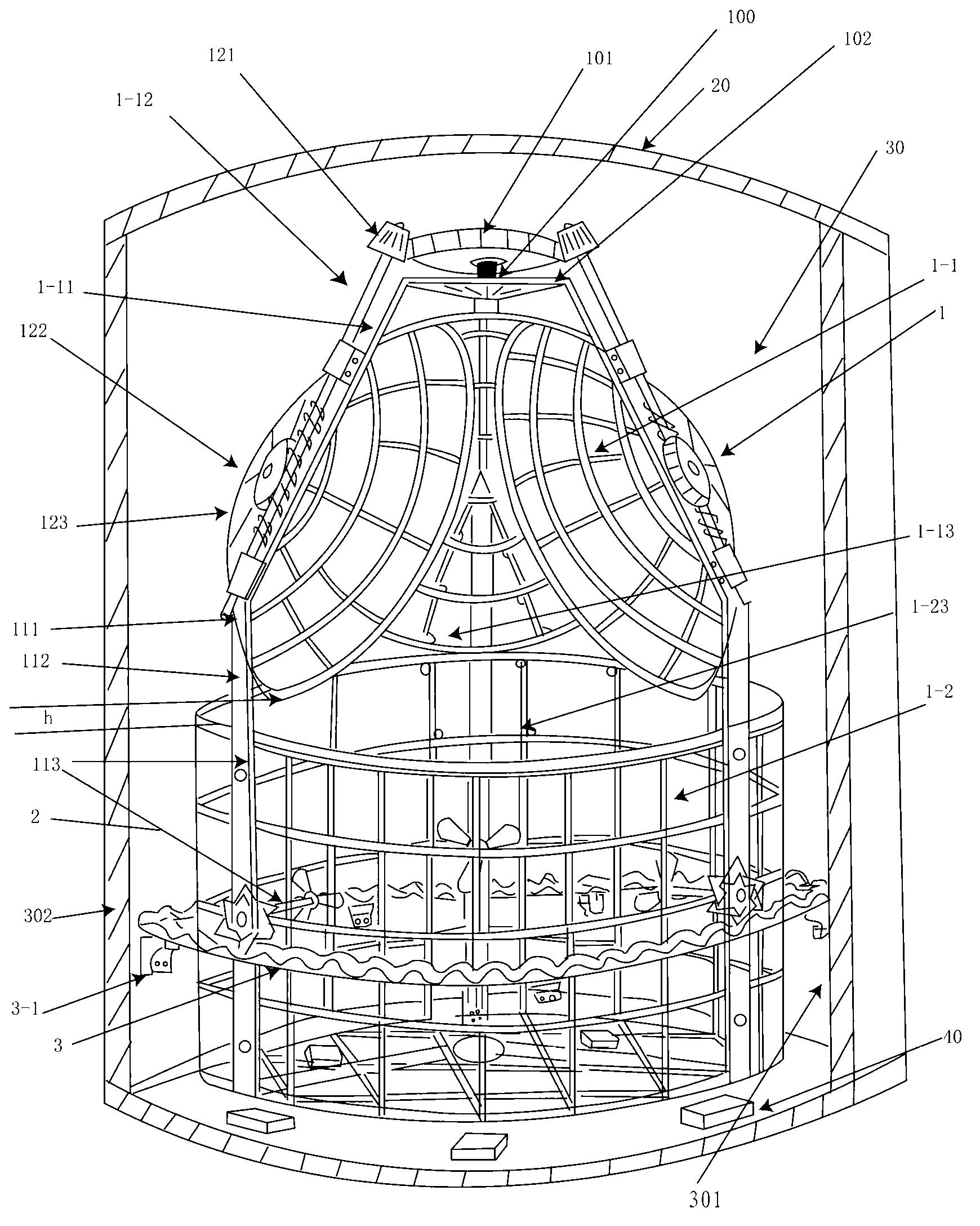
[0022] figure 1 It is a schematic diagram of the arrangement of the double rotary mechanism 1 in the vacuum chamber according to the present invention. This embodiment adopts an OLED coating machine composed of a double rotating mechanism 1 . This OLED coating machine includes a frame, a vacuum chamber 30 and a double rotating mechanism 1 configured inside the vacuum chamber 30, a plurality of molybdenum boats 40 and a power system for driving the double rotating mechan...


PUM


Abstract

The invention provides an OLED (organic light-emitting diode) coating machine with a dual-rotation mechanism. The OLED coating machine composed of a dual-rotation mechanism comprises a machine frame, a vacuum chamber, a dual-rotation mechanism, a plurality of molybdenum boats, a power system for driving the dual-rotation mechanism, a molybdenum boat electrifying heating system, a vacuum-pumping system, a vacuum chamber heating system and an instrument cabinet, wherein the dual-rotation mechanism, the molybdenum boats and the power system are arranged in the vacuum chamber; the instrument cabinet is composed of a dual-rotation mechanism speed indication and control subsystem, a vacuum-pumping system indication and control subsystem, a molybdenum boat electrifying heating indication and control subsystem, a film thickness indication and control subsystem, a vacuum chamber temperature indication and control subsystem, a general supply indication and control subsystem and other subsystems; the dual-rotation mechanism is composed of a rotation pot-shaped bracket positioned on the upper part in the vacuum chamber, a rotation cylindrical bracket positioned on the middle lower part of the vacuum chamber, and a gas disturbance homogenizing mechanism; and the rotation pot-shaped bracket and the rotation cylindrical bracket are respectively provided with a mechanism for fixing a workpiece subjected to vaporization coating, thereby facilitating the charging and discharging of the workpiece.

Description

technical field [0001] The invention relates to an OLED film coating machine, which is especially suitable for manufacturing OLEDs with larger dimensions. Background technique [0002] Vacuum evaporation is one of the main methods in the preparation process of OLED (Organic Light-Emitting Diode, organic light-emitting diode) devices. OLED devices need to evaporate multiple layers of organic thin films in a high-vacuum chamber, and the quality of the thin films is related to the quality and life of the device. At present, the evaporation of organic materials still has some disadvantages, such as low effective utilization rate (<10%), non-uniform dopant composition on the evaporation layer, uneven thickness of the evaporation layer, unstable evaporation rate, easy pollution of the vacuum chamber, etc. , resulting in that the coating uniformity of the sample substrate cannot meet the device requirements. [0003] No matter what type of equipment, the existing workpiece cla...

Claims


Application Information

Patent Timeline
Patent Type & Authority Applications(China)
IPC IPC(8): C23C14/50C23C14/24C23C14/12
Inventor 吕家东陈宗烈龚仕宏何荣开
Owner SOUTHEAST UNIV
Why Eureka
Try Eureka