exhaust system

A technology of exhaust system and exhaust pipe, which is applied in the direction of exhaust devices, gas chambers, gas channels, etc., and can solve the problems of expensive energy consumption and other issues

Inactive Publication Date: 2017-11-03
FAURECIA EMISSIONS CONTROL TECH GERMANY
View PDF7 Cites 0 Cited by
  • Summary
  • Abstract
  • Description
  • Claims
  • Application Information

AI Technical Summary

Problems solved by technology

Applying multi-component layers using flame spraying methods is also expensive and energy intensive

Method used


Image

  • exhaust system
  • exhaust system

Examples


Embodiment Construction

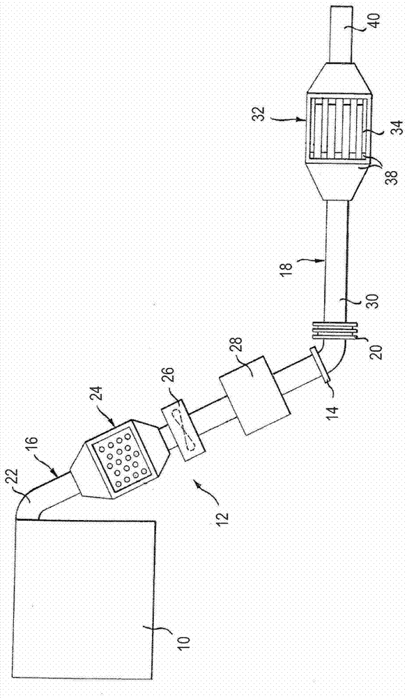
[0038] As an example, figure 1 An internal combustion engine 10 of a motor vehicle and a downstream exhaust system 12 are shown. The exhaust system 12 has a manifold section 16 extending as far as the flange 14 and a bottom section 18 adjoining the manifold section 16 downstream, the manifold section 16 and the bottom section 18 being connected to each other by a vibration decoupling device 20 .

[0039] The internal combustion engine 10 is adjoined by an exhaust pipe having a first pipe section 22 which leads to a particle receiving accumulator 24 having an oxidation catalytic converter.

[0040] Immediately downstream of the particulate receiving accumulator 24 , a turbocharger 26 is disposed in the manifold section 16 . Alternatively, the location of the particle receiving accumulator 24 and the location of the turbocharger 26 may also be interchanged. Also disposed in manifold section 16 , and more particularly downstream of particulate receiving accumulator 24 and turboch...


PUM


Abstract

The invention relates to an exhaust system for a motor vehicle having components made of coated sheet steel. The thickness of the steel plate is at most 4.5 mm and the steel plate is formed of ferritic stainless steel with a chromium content of 10.5% to 25%, a molybdenum content of 0% to 2.5%, a titanium and / or niobium content each Both range from 0.1% to 1.2%. The coating of the steel sheet consists of nickel.

Description

technical field [0001] The invention relates to an exhaust system for a motor vehicle comprising components made of coated steel sheets. Background technique [0002] Components of the exhaust system in a motor vehicle are typically made of high temperature and corrosion resistant materials such as stainless steel. Typically, such components are made of steel with a wall thickness of up to 10mm. In order to meet the guarantees given by the vehicle manufacturer for the service life of the exhaust system, higher wall thicknesses are required. For reasons of appearance, the components are usually provided with a base layer of nickel and a coating of chromium. [0003] Furthermore, it is also known to use steel sheets provided with an aluminum cladding. Although aluminum-clad steel plates are stable against thermal shock loads, they are not sufficiently resistant to trapped corrosive liquids such as exhaust condensate and are not sufficiently resistant to crevice corrosion. ...

Claims


Application Information

Patent Timeline
Patent Type & Authority Patents(China)
IPC IPC(8): F01N13/16F01N13/08F01N3/28F01N3/022C22C38/28C22C38/26
CPCF16L58/08F01N13/16F01N2530/04F16L9/02
Inventor 赫尔穆特·维泽尔乌韦·特勒格尔穆罕默德·亚西尔
Owner FAURECIA EMISSIONS CONTROL TECH GERMANY
Why Eureka
Try Eureka