Pulsation wire mesh catalytic burning device and method

A wire mesh and catalytic combustion technology, which is applied in the direction of combustion method, combustion type, incinerator, etc., can solve the problems that the reaction rate is controlled by diffusion, and the preparation process of the wire mesh carrier is complicated, and achieves a simple and compact structure. , The effect of less pollutant discharge

Inactive Publication Date: 2013-08-14
INST OF PROCESS ENG CHINESE ACAD OF SCI
View PDF6 Cites 2 Cited by
  • Summary
  • Abstract
  • Description
  • Claims
  • Application Information

AI Technical Summary

Problems solved by technology

[0010] The present invention aims at many deficiencies existing in the existing monolithic wire mesh catalytic combustion, and provides a pulsating wire mesh catalytic combustion device for volatile organic pollutants, which solves the problem that the reaction rate in the prior art is affected by diffusion. Control or complex issues of wire mesh carrier molding preparation process

Method used


Image

  • Pulsation wire mesh catalytic burning device and method

Examples


Embodiment 1

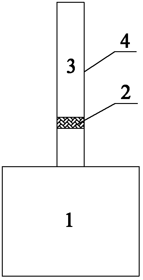
[0037]The pulsating wire mesh catalytic combustion device of the present invention is composed of an acoustic decoupling chamber, a Rijke type pulsating burner body, a wire mesh catalytic bed, and a heat exchange cooling device, wherein the integral metal mesh catalytic bed has a three-dimensional The honeycomb wire mesh carrier with a mesh structure is located at 1 / 4 of the height of the Rijke tube on the upper part of the acoustic decoupling chamber to meet the needs of production processes such as rubber, synthetic leather, pharmaceuticals, enameled wire, printed matter, shoes, paint, etc. Purification of volatile organic pollutants (VOCs) is required.

Embodiment 2

[0039] The pulsating wire mesh catalytic combustion device of the present invention is composed of an acoustic decoupling chamber, a Rijke type pulsating burner body, a metal mesh catalytic bed, and a heat exchange cooling device. The metal mesh catalytic bed layer at the height of 8-1 / 3 is stacked by several short-channel wire meshes with sinusoidal structure, triangular structure or square structure to meet the pollutants in organic waste gas emitted from stationary sources (such as Hydrocarbons, halogenated hydrocarbons, aromatic hydrocarbons, polycyclic aromatic hydrocarbons, acetone, pyridine, ethyl acetate, etc.) purification needs.

Embodiment 3

[0041] The pulsating wire mesh catalytic combustion device of the present invention is composed of an acoustic decoupling chamber, a Rijke type pulsating burner body, a metal mesh catalytic bed, and a heat exchange cooling device. The metal mesh catalytic bed at the height of 8~1 / 2 is composed of upper and lower metal mesh catalytic beds. The bottom catalytic layer is mainly used for the oxidation reaction of hydrogen, while the top catalytic layer is mainly used for the oxidation reaction of CO. In order to meet the needs of blast furnace gas, synthesis gas-based metallurgical reducing gas tail gas, biomass and combustible waste gasification gas rich in H, which are mainly evacuated in the iron and steel industry 2 The efficient utilization of low calorific value gases and the need for pollutant emission reduction.


PUM


Abstract

The invention relates to the technical field of catalytic burning, in particular to a pulsation wire mesh catalytic burning device and method. The device comprises a sound decoupling chamber (1) and a Rijke pipe (3) and further comprises a wire mesh catalytic bed layer (2) arranged in a Rijke type pulsation wire mesh catalytic burner main body. Compared with the prior art, the device and method has the advantages of being high in catalytic burning efficiency, less in pollutant discharge, simple and compact in structure and less in investment, reducing resistance, reducing boundary layer flowing resistance due to the fact that air flow is in the pulsation state and reducing air flow resistance correspondingly when the air flow passes through the wire mesh catalytic bed layer. The device and method can be used for purifying volatile organic contaminant (VOCs) discharged by a fixed source and can also be used for high-efficiency utilization of low heating value combustible rich-hydrogen gas like blast furnace gas and contaminant emission reduction.

Description

technical field [0001] The invention relates to the technical field of catalytic combustion, in particular, the invention relates to a pulsating wire mesh catalytic combustion device and a combustion method. Background technique [0002] Volatile organic pollutants (VOCs), such as hydrocarbons, halogenated hydrocarbons, aromatic hydrocarbons, polycyclic aromatic hydrocarbons, acetone, Pyridine, ethyl acetate, etc., are an important class of toxic organic pollutants in the environment, which are extremely harmful to human health. Continuously strict environmental protection laws and regulations have promoted the research and development of such pollutant removal technologies. For this reason, catalytic combustion technologies that effectively eliminate VOCs have attracted widespread attention. [0003] Honeycomb ceramic catalytic combustion technology is an effective method widely used in industry to eliminate VOCs. It has the advantages of low resistance drop, stable purifi...

Claims


Application Information

Patent Timeline
IPC IPC(8): F23G7/07
Inventor 汤根土胡万起李竹川王晓岚
Owner INST OF PROCESS ENG CHINESE ACAD OF SCI
Why Eureka
Try Eureka