Control system and method for high-precision needle valve orifice grinding

A control system and grinding technology, applied in grinding devices, grinding machine tools, metal processing equipment, etc., can solve the problems of constantly changing calculation flow time interval, unpredictable control, etc., to achieve simple cutting and configuration, improved flow consistency, Develop convenient effects

Inactive Publication Date: 2013-08-21
SHANGHAI UNIV +2
View PDF6 Cites 4 Cited by
  • Summary
  • Abstract
  • Description
  • Claims
  • Application Information

AI Technical Summary

Problems solved by technology

For this system, if the flow is constantly changing, the pulse cycle time of the M3 measured flows is also changing, which is manifested as the time interval for calculating the flow is constantly changing, and cannot be predicted and controlled

Method used


Image

  • Control system and method for high-precision needle valve orifice grinding
  • Control system and method for high-precision needle valve orifice grinding
  • Control system and method for high-precision needle valve orifice grinding

Examples


Embodiment 1

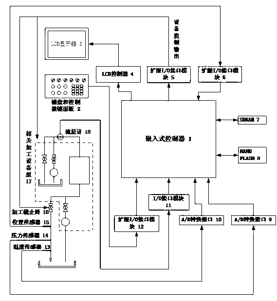
[0042] Such as figure 1 As shown, the control system of the high-precision needle valve body nozzle hole grinding process of the present invention includes an embedded controller 1, a keyboard and control button panel 2, an LCD display 3, an LCD controller 4, and three extensions 1 / O interface modules 5, 6 and 12, an I / O interface module 11, a SDRAM 7, a NAND FLASH 8, two A / D conversion interfaces 9 and 10, a temperature sensor 13 and a pressure sensor 14, a position Sensor 15, a processing cut-off valve 16, a related processing equipment group 17 and a flow meter 18 are characterized in that: the embedded controller 1 is connected with SDRAM 7 and NAND FLASH 8 to form the core module of the control system, providing control The basic environment of system software operation; the embedded controller 1 is connected with the keyboard and the control button panel 2 through the first expansion I / O interface module 12, and receives instructions sent from the keyboard and the contr...

Embodiment 2

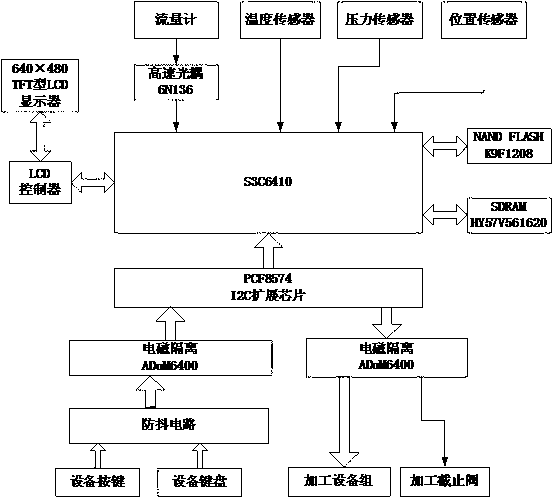
[0044] Such as figure 2 Shown, a kind of control unit of control system of the present invention, wherein embedded controller selects the embedded processing chip S3C6410 of ARM11 series of Samsung Company, NAND FLASH is K9F1208 of Samsung Company, SDRAM is HY57V561620 of Hynix Semiconductor Company, NAND FLASH K9F1208 stores the firmware program running on the system, including BootLoader startup program, ReWorks strong real-time operating system program, initialization program and control system working program. After power-on, the firmware program in NAND FLASH K9F1208 is loaded into SDRAM HY57V561620 for operation. After initialization, the system enters the working program of the control system. S3C6410 receives the isolated flow pulse signal from the flowmeter through the high-speed optocoupler of NEC company. Receive the temperature and pressure analog signals sent by the temperature sensor and pressure sensor, and receive the position signal of the position sensor...

Embodiment 3

[0046] The I / O interface module and the extended I / O interface module of the control system of the present invention.

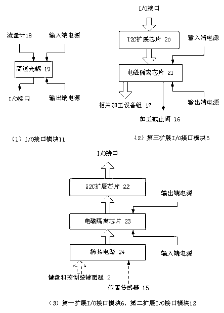
[0047] Such as image 3 As shown in (1), the I / O interface module 11 described in Embodiment 1 includes a high-speed optocoupler 19, which is characterized in that: the input end of the high-speed optocoupler 19 is connected to the flowmeter 18, and is connected to the The input end is connected to the power supply, and the output end of the high-speed optocoupler 19 is connected to the I / O interface of the embedded controller 1 and connected to the output end power supply.

[0048] Such as image 3 As shown in (3), the first extended I / O interface module 6 and the second extended I / O interface module 12 described in Embodiment 1 include an I2C extension chip 22, an electromagnetic isolation chip 23 and an anti-shake circuit 24 , it is characterized in that: described anti-shake circuit 24 is connected with keyboard and control button panel 4 or positio...


PUM


Abstract

The invention relates to control system and method for high-precision needle valve orifice grinding. The control system comprises an embedded controller, a keyboard, a control key panel, an LCD (liquid crystal display), an LCD controller, three extended I/O (input/output) interface modules, an I/O interface module, a SDRAM (synchronous dynamic random access memory), an NAND flash, two A/D (analog/digital) conversion interfaces, a temperature sensor, a pressure sensor, a position sensor, a machining stop valve, a related machining unit, and a flowmeter. The basic environment combining an embedded ARM (advanced RISC machine) controller based on RISC (reduced instruction set computer) and a high-real-time embedded operating system ReWorks is used; a logic control main program and a flow processing subprogram stored in the embedded controller are used; and accordingly the control method is achieved. In an ideal case, flow uniformity of a machined needle valve orifice reaches +/-0.5% and reaches the international advanced level. The control system and method are also applicable to the field of control of other types of high-precision real-time machining.

Description

technical field [0001] The invention relates to a control system and method for high-precision needle valve body nozzle hole grinding. The system and method can also be widely used in various types of high-precision real-time processing control fields. Background technique [0002] The engine of a diesel engine is the core component of a diesel engine, and the performance of the engine is related to many factors. Among them, the flow consistency of the injectors between the cylinders, that is, the size of the flow deviation has a great influence on the overall performance of the engine. If the flow deviation is large, the torque between the cylinders of the engine will increase, the output power will decrease, the engine will vibrate greatly, the noise will be large, and the combustion will be insufficient, and the smoke emission will be large. With the continuous improvement of automobile emission standards, the requirements for the flow deviation of diesel engine fuel in...

Claims


Application Information

Patent Timeline
Patent Type & Authority Applications(China)
IPC IPC(8): B24B37/005
Inventor 蔡红霞柏余杰王文斌俞涛徐翀
Owner SHANGHAI UNIV
Why Eureka
Try Eureka