Heating element, steam cutting device, and burner of a power-enerating device

A technology of heating elements and cutting equipment, applied in lighting and heating equipment, burners, electric heating devices, etc., can solve the problems of inability to obtain effective power generation, constant temperature difference, inability to charge gently, inability to have stable combustion, etc., and achieve improvement Manipulation, size reduction, evaporative effects

Active Publication Date: 2013-08-21
FRONIUS INTERNATIONAL GMBH
View PDF12 Cites 4 Cited by
  • Summary
  • Abstract
  • Description
  • Claims
  • Application Information

AI Technical Summary

Problems solved by technology

In contrast, batteries or energy storage devices with a relatively high capacity, for example above 30 Ah, as is the case with energy storage devices of vehicles, in particular motor vehicles, cannot be charged gently and efficiently
Also, with the burner used, the so-called worm burner, there cannot be a stable combustion such that the constant temperature difference required for efficient power generation cannot be obtained

Method used


Image

  • Heating element, steam cutting device, and burner of a power-enerating device
  • Heating element, steam cutting device, and burner of a power-enerating device
  • Heating element, steam cutting device, and burner of a power-enerating device

Examples


Embodiment Construction

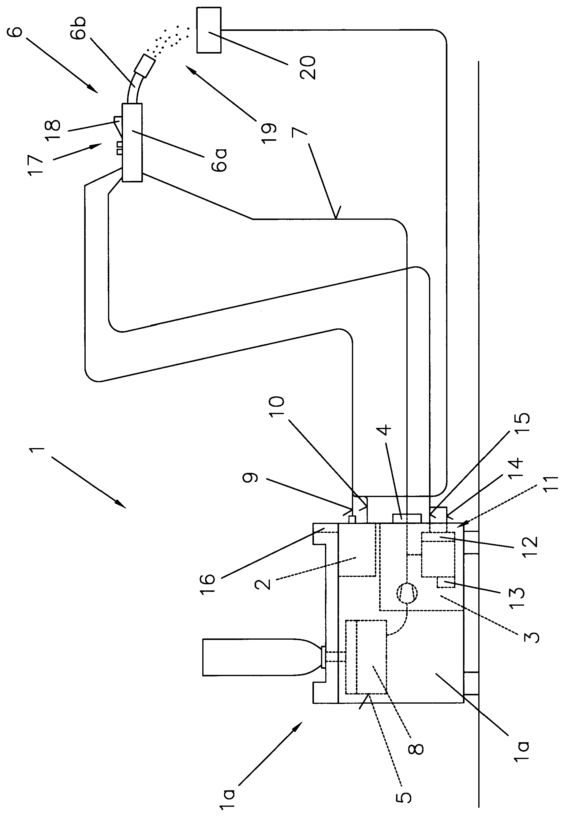
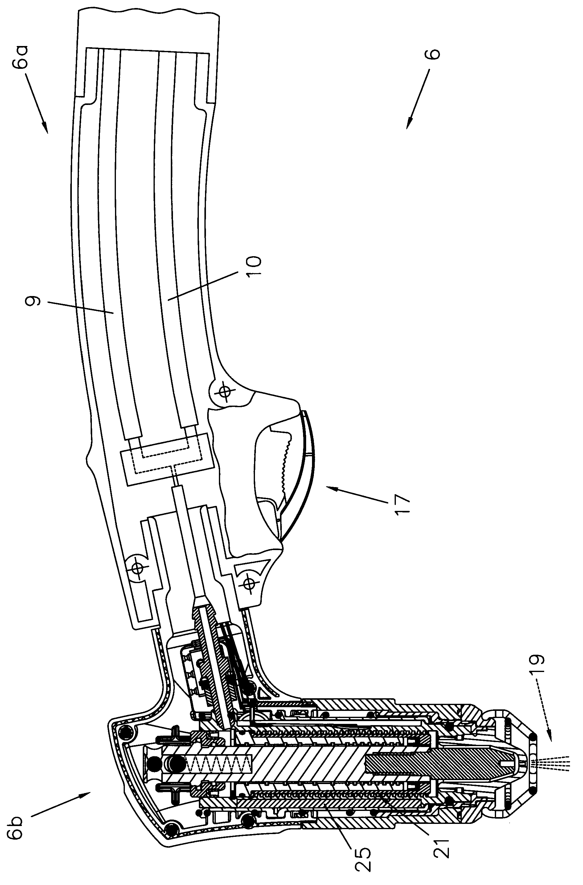
[0028] figure 1 A steam cutting device 1 for a steam cutting process is shown. The basic device 1 a of the steam cutting device 1 comprises a power source 2 , a control device 3 and a blocking element 4 assigned to the control device 3 . The blocking element 4 is connected via a supply line 7 to the container 5 and to the burner or plasma burner 6 comprising the burner handle 6 a and the burner part 6 b, so that the liquid 8 provided in the container 5 can be supplied to the burner 6 . Burner 6 is supplied with electrical energy from power source 2 via lines 9 , 10 .

[0029] For cooling the burner 6 , the latter is connected via a cooler circuit 11 to the container 5 or its own liquid container 13 , preferably via an interposed flow monitor 12 . During operation of the burner 6 or the base unit 1 a , the control unit 3 activates the cooler circuit 11 , so that the burner 6 can be cooled via the cooler circuit 11 . To form the cooler circuit 11 , the steam plasma burner 6 i...


PUM


Abstract

The invention relates to a heating element (25) for liquids to be vaporised as well as a burner (6) of a steam cutting device (1) and a burner (38) of a power-generating device, said element being designed as an induction heater (47) comprising one coil (25a). In order to improve vaporisation, the coil (25a) of the induction heater (47) is enclosed in a hybrid construction which is composed of a main part (31) with laterally extending webs (33), and which consists of an easily magnetisable material (35) and a thermally highly-conductive material, a covering element (32) consisting of nanocrystalline materials being arranged on said webs (33), and the easily magnetisable material (35) being designed to be installed on a thermally highly-conductive material (37) of a vaporiser (21).

Description

technical field [0001] The invention relates to a heating element for liquid evaporation, for example of a burner of a steam cutting device or a burner of an electric power plant, said element being designed as an induction heater comprising a coil. [0002] In addition, the present invention relates to a steam cutting device comprising said heating element and a burner comprising said heating element of a power generation device of a charging device. Background technique [0003] From EP1050200B1 a steam cutting device is known which consists of a burner, a control device, a liquid supply system and a power source. The burner is connected by wiring to a power source and by a supply line to a liquid supply system. At least one channel or fluid channel with a given cross section is arranged in the burner, in which channel the liquid is converted into a gaseous state. In addition, the burner includes at least a cathode and an anode, and the liquid source is connected to the ...

Claims


Application Information

Patent Timeline
Patent Type & Authority Applications(China)
IPC IPC(8): H05H1/34F23D11/44
CPCB23K9/013B23K10/00F23D11/448F23D14/42F23D14/66H05B6/108H05H1/34Y02E20/34F22B1/281
Inventor 马克斯·施特格尔克里斯蒂安·梅格约瑟夫·莱布克里斯蒂安·雷施丹尼尔·普拉策
Owner FRONIUS INTERNATIONAL GMBH
Why Eureka
Try Eureka