Method for producing bandwidth tunable slow light in polymer filling photonic crystal slot waveguide

A photonic crystal slot and production method technology, applied in the directions of light guides, optics, optical components, etc., can solve the problems of limiting the slow light application range of photonic crystal slot waveguides, changing slow light characteristics, and working wavelength drift, and reducing the difficulty of process exploration. 、Various structural parameters, optimizing the effect of slow light characteristics

Inactive Publication Date: 2013-08-28
NORTHEASTERN UNIV
View PDF3 Cites 10 Cited by
  • Summary
  • Abstract
  • Description
  • Claims
  • Application Information

AI Technical Summary

Problems solved by technology

In addition, when the external environment changes or there is an error in the preparation process, it is easy to cause a change in the characteristics of the slow light or a shift in its working wavelength [Document 9. H. Aghababaeian, M. H. Vadjed-Samiei, N. Granpayeh. "Temperature stabilization of group index in silicon photonic crystal waveguides.” Journal of the Optical Society of Korea, 2011, 15(4): 398-402; Literature 10. W. W. Song, R. A. Integlia, and W. Jiang. Slow light loss due to roughness in photonic crystal waveguides : An analytic approach [J]. Physical Review B, 2010, 82(3): 235306.], these will seriously limit the application range of photonic crystal slot waveguide slow light

Method used


Image

  • Method for producing bandwidth tunable slow light in polymer filling photonic crystal slot waveguide
  • Method for producing bandwidth tunable slow light in polymer filling photonic crystal slot waveguide
  • Method for producing bandwidth tunable slow light in polymer filling photonic crystal slot waveguide

Examples


Embodiment Construction

[0026] In order to make the purpose, technical solution and advantages of the present invention clearer, the specific structure, principle and slow light characteristic optimization process of the present invention will be further described in detail below in conjunction with specific embodiments and with reference to the accompanying drawings.

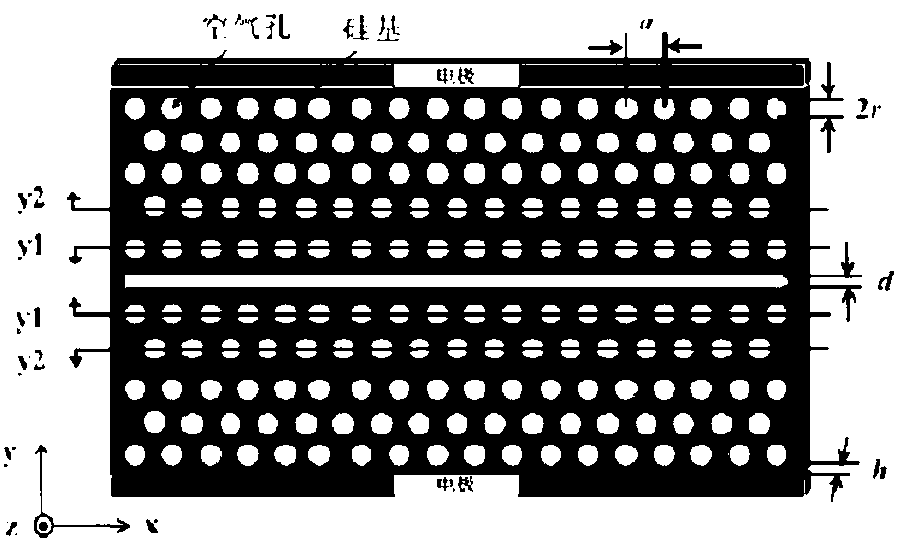
[0027] The present invention proposes a method for generating broadband tunable slow light in a polymer-filled photonic crystal slot waveguide, such as figure 1 Shown is a schematic diagram of the structure of a polymer-filled photonic crystal slot waveguide based on electro-optic modulation. A photonic crystal waveguide with a W1 structure is formed by removing the middle row of air holes along the x direction in an ordinary triangular lattice photonic crystal, and then at the center of the defect Place a row with a width of d =0.32 a The air slots form a photonic crystal slot waveguide structure. in, a =341nm is the photonic crys...


PUM

PropertyMeasurementUnit
thicknessaaaaaaaaaa
refractive indexaaaaaaaaaa

Abstract

The invention provides a method for producing bandwidth tunable slow light in a polymer filling photonic crystal slot waveguide. According to the method for producing the bandwidth tunable slow light in the polymer filling photonic crystal slot waveguide, the characteristics of slow light in the photonic crystal slot waveguide are optimized through the adjustment of the positions of air holes in two sides of an air slot, when a group refractive index is 55, the wavelength range, namely the bandwidth, of a smooth slow light area can reach 9.0nm, when the group refractive index is 100, the wavelength range, namely the bandwidth, of the smooth slow light area can reach 3.5nm, when the group refractive index is 172.5, the wavelength range, namely the bandwidth, of the smooth slow light area can reach 1.1nm, when the group refractive index is 222, the wavelength range, namely the bandwidth, of the smooth slow light area can reach 0.8nm, and for example, when 0V driving voltage, or 2V driving voltage, or 4V driving voltage, or 6V driving voltage, or 8V driving voltage, or 10V driving voltage is applied to slow light with the group refractive index of 100 and the bandwidth of 3.5nm respectively, the central operating wavelength of the slow light is 1562nm, 1560.5nm, 1559nm, 1557.5nm, 1556nm, and 1554.5nm respectively. Meanwhile, when the group refractive index is between 90 and 110, the bandwidth of the slow light is increased to 111nm, and the bandwidth tunable slow light is achieved.

Description

technical field [0001] The invention relates to a method for generating broadband tunable slow light in a polymer-filled photonic crystal groove waveguide, and belongs to the technical field of micro-optoelectronic device design. Background technique [0002] Photonic crystals, also known as optical semiconductors, are new artificial materials formed by periodic arrangements of substances with different dielectric constants on the scale of light wavelengths. Its unique photonic band gap and photon localization characteristics enable people to manipulate The movement of photons becomes possible [Document 1. A. Scherer, O. Painter, J. Vuckovic, M. Loncar, and T. Yoshie. Photonic crystals for confining, guiding, and emitting light. IEEE Transactions on Nanotechnology, 2002, 1( 1): 4-11.]. A line defect is introduced in the photonic crystal along the direction of light propagation to form a photonic crystal waveguide. At this time, the photonic crystal waveguide will be affecte...

Claims


Application Information

Patent Timeline
Patent Type & Authority Applications(China)
IPC IPC(8): G02B6/122G02F1/035G02F1/365G02F1/355
Inventor 赵勇张亚男王琦
Owner NORTHEASTERN UNIV
Why Eureka
Try Eureka