Novel carbon dioxide trapping device performing liquefaction and then sublimation

A carbon dioxide and capture device technology, applied in the direction of inorganic chemistry, carbon compounds, chemical instruments and methods, etc., can solve problems such as difficult equipment management, high requirements for raw material gas, and complicated membrane production process, so as to avoid serious corrosion and save energy. The effect of liquefaction energy consumption and capture rate improvement

Inactive Publication Date: 2013-09-04
SOUTHEAST UNIV
View PDF0 Cites 10 Cited by
  • Summary
  • Abstract
  • Description
  • Claims
  • Application Information

AI Technical Summary

Problems solved by technology

The solution absorption method has mature technology and is widely used, but this method requires a lot of heat in the regeneration stage, which leads to high energy consumption. The preparation of absorbent requires a lot of energy and the absorbent is corrosive and toxic. At the same time, the absorbent is repeatedly absorbed and regenerated. It will fail during the process and needs to be continuously replenished; the pressure swing adsorption method has no corrosive medium and low operation and maintenance costs, but in order to obtain higher carbon dioxide purity, more adsorption towers are needed, equipment management is more difficult, and the investment is relatively high; Membrane separation The process of this method is simple and easy to operate, but it has high requirements for raw material gas, the processing capacity is small at this stage, the membrane making process is complicated, and the membrane stability is poor.
The above commonly used methods still have a common problem, that is, the separated carbon dioxide products are all gases, which require energy consumption to be further processed into liquids for transportation and storage.
In addition, the purity of the separated and captured carbon dioxide products is generally difficult to meet the specifications for direct application. If the captured carbon dioxide needs to be applied to various industries, further purification is required

Method used


Image

  • Novel carbon dioxide trapping device performing liquefaction and then sublimation

Examples


Embodiment Construction

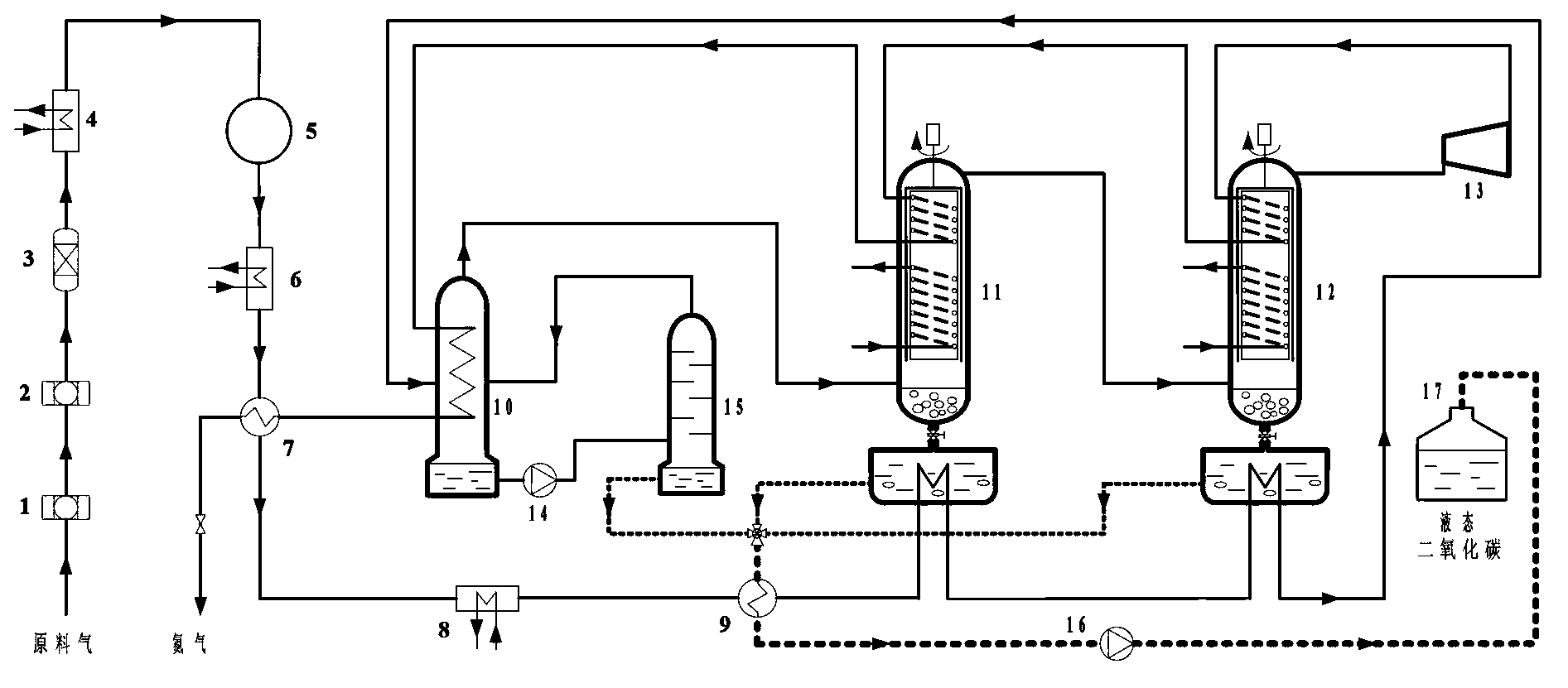
[0019] The present invention will be further explained below in conjunction with the accompanying drawings.

[0020] Such as figure 1 As shown, a new type of carbon dioxide capture device for liquefaction and recondensation, which includes a filter 1, an adsorber 2, a dryer 3, a first heat exchanger 4, a compressor 5 and a second heat exchanger 6 connected in sequence . The raw gas passes through the filter 1, the adsorber 2 and the dryer 3, so that the raw gas is dried and purified before the carbon dioxide gas is captured; some solid impurities are removed through the filter 1, and then the acid gas is absorbed through the adsorber 2, and finally Moisture is removed by dryer 3. Compared with the alcohol amine absorption method widely used at present, this system does not use solvents for chemical reactions such as alcohol amine, which avoids the generation of toxic substances and serious corrosion of equipment.

[0021] The outlet of the second heat exchanger 6 is connect...


PUM


Abstract

The invention discloses a novel carbon dioxide trapping device performing liquefaction and then sublimation. According to the device, research on physical properties of carbon dioxide and related mixtures is combined, and gas-liquid separation is performed firstly through a low temperature mode to obtain a part of liquid carbon dioxide; mixed gas after the liquefaction separating is cooled continuously and passes through two sublimation separating towers, and then carbon dioxide is separated; and dry ice obtained from sublimation separation is collected into a condensation pool, and the pressure is controlled above triple point pressure of carbon dioxide, so that the obtained dry ice can be melted directly into liquid carbon dioxide. The overall system design facilitates sufficient cold quantity recovery. The device improves the carbon dioxide trapping purity effectively, increases the carbon dioxide trapping efficiency, improves the cold quantity recovery rate of the system, and is energy-saving and low in consumption.

Description

technical field [0001] The invention separates carbon dioxide from raw material gas rich in carbon dioxide through compression and cooling, and belongs to the technical field of refrigeration and low temperature. Background technique [0002] While the rapid industrial development process brings people convenient life, it also brings huge environmental problems to people. According to the statistics of the US Department of Energy, the annual emission of carbon dioxide due to the burning of fossil fuels reaches more than 30 billion tons, and it is still growing . Heavy industries such as power plants burning fossil fuels, oil plants, and steel plants are the main sources of carbon dioxide emissions. The volume content of carbon dioxide in the flue gas emitted by power plants is about 15%, and the volume content of carbon dioxide in the flue gas emitted by some metallurgical plants is higher than that of power plants. About 35%. In addition to the large amount of carbon diox...

Claims


Application Information

Patent Timeline
Patent Type & Authority Applications(China)
IPC IPC(8): C01B31/20C01B32/50
CPCY02A50/20
Inventor 李舒宏李献亮张小松丁洁
Owner SOUTHEAST UNIV
Why Eureka
Try Eureka