Device and method for quenching dry-method treatment and sensible heat recovery of high-temperature molten slag

A waste heat recovery device and slag technology, which are applied in waste heat treatment, energy efficiency improvement, lighting and heating equipment, etc., can solve the problems of complex structure of granulation device, distance for industrial application, and reliability to be improved, etc. Industrialized production, good application prospects, the effect of reducing energy consumption

Active Publication Date: 2013-09-25
NORTHEASTERN UNIV
View PDF4 Cites 20 Cited by
  • Summary
  • Abstract
  • Description
  • Claims
  • Application Information

AI Technical Summary

Problems solved by technology

The wind crushing method uses high-speed air jets to granulate the molten slag to obtain solid slag particles, and uses cold air as the cooling medium to recover the waste heat of the slag particles. The overall vitrification rate of the slag particles obtained by the wind crushing method is greater than 95%. The waste heat recovery rate is about 48%; however, the wind crushing method has problems such as large power consumption, large floor space, and high overall cost.
The basic principle of the centrifugal granulation method is to use the centrifugal force of the rotating cup to granulate the hig

Method used


Image

  • Device and method for quenching dry-method treatment and sensible heat recovery of high-temperature molten slag

Examples


Example Embodiment

[0036] Example 1

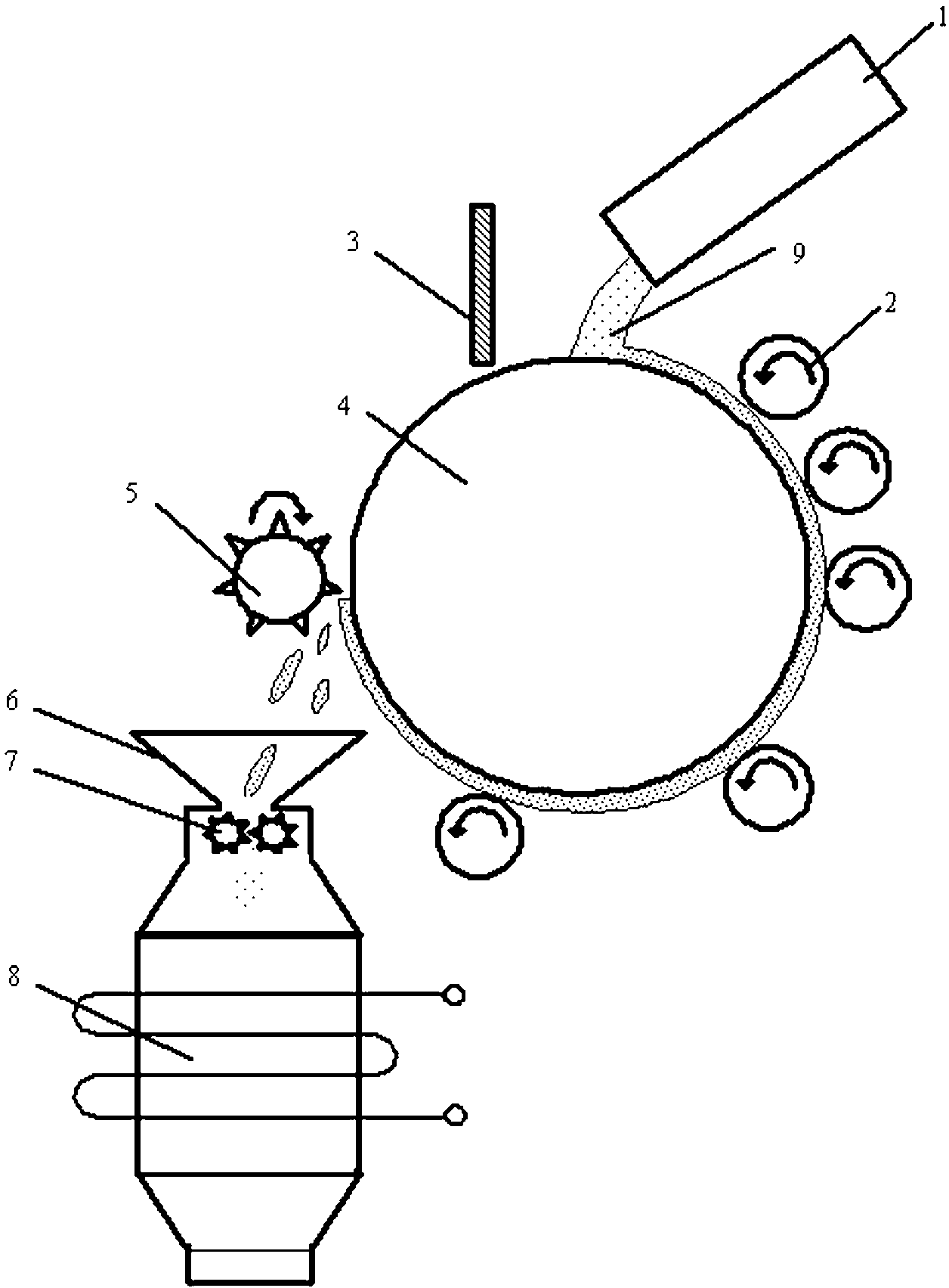
[0037] The structure of the device for rapid cooling and dry treatment of high temperature molten slag and recovery of sensible heat is as follows figure 1 As shown, it includes a slag guide groove 1, a slag stopper 3, a rotating drum 4, a cooling roller group, a slag removal roller 5, a slag particle collector 6 and a waste heat recovery device 8; a slag stopper 3, a slag guide groove 1, a cooling roller The group and the slag removal roller 5 are arranged on the outer surface of the drum 4 along the direction of rotation of the drum 4. The slag guide groove 1 and the slag stopper 3 are respectively located on the upper two sides of the top of the drum 4, the slag roller 5 and the slag stopper There is a gap between 3 and drum 4, the distance between the cooling roller set and the outer surface of the drum 4 is 5mm, and the distance between the slag guide groove 1 and the outer surface of the drum 4 is 100mm; There is a slag particle collector 6, a crusher 7 ...

Example Embodiment

[0051] Example 2

[0052] The structure of the device for processing and recovering sensible heat by rapid cooling and drying of high-temperature molten slag is the same as that of the first embodiment.

[0053] (1) The waste heat recovery device is a fixed bed, and the cooling medium is air;

[0054] (2) The cooling roll group is composed of 4 water-cooled rolls;

[0055] (3) The distance between the cooling roller set and the outer surface of the drum is 30mm;

[0056] (4) The distance between the slag guide groove and the outer surface of the drum is 400mm;

[0057] The method of quenching and drying high temperature molten slag and recovering sensible heat is the same as that of Example 1, the difference lies in:

[0058] (1) After crushing, the granular slag is formed into the fixed bed, and normal temperature air is passed into the fixed bed to exchange heat with the granular slag, forming hot air to absorb the heat, and the granular slag is discharged after the waste heat is recove...

Example Embodiment

[0063] Example 3

[0064] The structure of the device for processing and recovering sensible heat by rapid cooling and drying of high-temperature molten slag is the same as that of the first embodiment.

[0065] (1) The waste heat recovery device is a fixed bed, and the cooling medium is air;

[0066] (2) The cooling roll group is composed of 12 water-cooled rolls;

[0067] (3) The distance between the cooling roller set and the outer surface of the drum is 60mm;

[0068] (4) The distance between the slag guide groove and the outer surface of the drum is 800mm;

[0069] The method of rapid cooling and dry treatment of high temperature molten slag and recovery of sensible heat is the same as that of Example 1. The difference lies in:

[0070] (1) After pulverization, the granular slag is formed into the fluidized bed, and normal temperature air is passed into the fluidized bed to exchange heat with the granular slag, forming hot air to absorb the heat, and the granular slag is discharged a...


PUM

PropertyMeasurementUnit
Granularityaaaaaaaaaa

Abstract

The invention discloses a device and a method for quenching dry-method treatment slag and sensible heat recovery of high-temperature molten, wherein a slag stop plate, a slag guide groove, a cooling roll group and a slag removal roll in the device are sequentially arrayed on the outer surface of a rotary drum along the rotation direction of the rotary drum; a slag particle collector is arranged below the slag removal roll; a crusher is arranged on the lower part of the slag particle collector; a waste heat recovery device is arranged below the crusher. The method comprises the following steps of: placing the high-temperature molten slag on the surface of the rotating rotary drum via the slag guide groove; conveying the high-temperature molten slag to a space between the rotary drum and the cooling roll group by the rotary drum; extruding the high-temperature molten slag to be shaped like sheets, cooling and solidifying the high-temperature molten slag to form glass-body solid slag, and conveying the glass-body solid slag to the position of the slag removal roll; peeling the glass-body solid slag, and conveying the glass-body solid slag in the waste heat recovery device; dropping the glass-body solid slag in the crusher, and then forming particle slag after crushing; and then conveying the particle slag in the waste heat recovery device. The method disclosed by the invention has the characteristics of being simple to operate, suitable for industrialized production, capable of alleviating environmental pollution, low in process cost, and the like, as well as has a good application prospect.

Description

technical field [0001] The invention relates to high-temperature slag utilization technology, in particular to a device and method for rapid cooling and dry processing of high-temperature slag and recovery of sensible heat. Background technique [0002] There are a large number of high-temperature slags in the industrial field, such as blast furnace slag, steel slag, copper slag, nickel slag, etc.; the temperature of these slags is mostly around 1500 °C; the total amount is measured in hundreds of millions of tons, which is a high-quality waste heat resource. It has high recycling value. [0003] Taking the blast furnace slag with the largest amount as an example, the current treatment of blast furnace slag is mainly based on the water quenching process, that is, the blast furnace slag is quenched with a large amount of water, and the formed water quenched slag has a glass body content of more than 95%. , has good hydration activity, and can be used to produce building mater...

Claims


Application Information

Patent Timeline
IPC IPC(8): C21B3/08F27D17/00
CPCY02P10/25
Inventor 于庆波胡贤忠刘军祥秦勤
Owner NORTHEASTERN UNIV
Why Eureka
Try Eureka