IGBT module parallel connection protection circuit applied to high-power inverter

A technology for protecting circuits and inverters, applied to emergency protection circuit devices, electrical components, etc., can solve problems such as desaturation, IGBT module overheating damage, overheating, etc.

Active Publication Date: 2013-09-25
ZHEJIANG HAIDE NEW ENERGY
View PDF4 Cites 10 Cited by
  • Summary
  • Abstract
  • Description
  • Claims
  • Application Information

AI Technical Summary

Problems solved by technology

The driving scheme of its design is shown in Figure 3 attached to the manual , the cable for Vce saturation voltage drop detection of IGBT modules V11 and V21 ( In Figure 3, the detection cables are: VCE_SAT) are connected together, which makes the driver unable to effectively identify short-circuit faults and perform related protection. During the short-circuit process, the current of the IGBT module increases sharply, and after reaching a certain value (generally 4 times rated current) there will be desaturation phenomenon
If the protection is not timely (generally within 10us), the IGBT module will be overheated and damaged, so it is necessary to correctly identify the through fault
[0005] When the IGBT module is over-current and desaturation occurs, if the IGBT module is turned off quickly (the current drops too fast), the collector will appear when the IGBT module is turned off. The voltage spike between the emitter and the emitter (referred to as the CE voltage spike) exceeds the rated voltage, causing the CE voltage and current operating point of the IGBT module to exceed its safe operating area (RBSOA) and damage
An existing solution to the voltage spike between CEs in drive distribution is an active clamping circuit, as shown in the attached Figure 4, that is, after the voltage across CE exceeds the set value (for example, 1400V) during the IGBT turn-off process, through the regulator Z13 and diode D11 (or The feedback circuit composed of Zener diode Z23 and diode D21) raises the gate voltage of the IGBT module above its threshold voltage, and makes the IGBT module in a short-term conduction, thereby suppressing the overvoltage spike between CEs. Although this scheme is In the case of a short circuit fault, it can effectively reduce the overvoltage risk of the IGBT module, but the disadvantage is that the circuit is complex, and if the DC bus operating voltage is high, the active clamp circuit will work frequently, which will eventually cause the TVS tube to overheat and fail.

Method used


Image

  • IGBT module parallel connection protection circuit applied to high-power inverter
  • IGBT module parallel connection protection circuit applied to high-power inverter
  • IGBT module parallel connection protection circuit applied to high-power inverter

Examples


Embodiment Construction

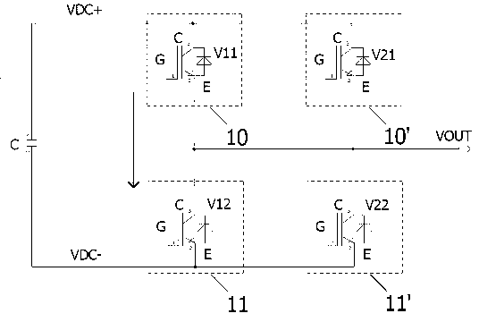
[0015] A parallel protection circuit for IGBT modules applied to high-power inverters, a parallel protection circuit for IGBT modules applied to high-power inverters, the parallel protection circuit includes a circuit for realizing safe shutdown of IGBT modules A soft-off module 5 , the soft-off module 5 is respectively connected to a plurality of saturation voltage drop detection modules, and the plurality of saturation voltage drop detection modules are respectively connected to a feedback optocoupler module 7 .

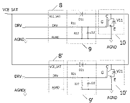
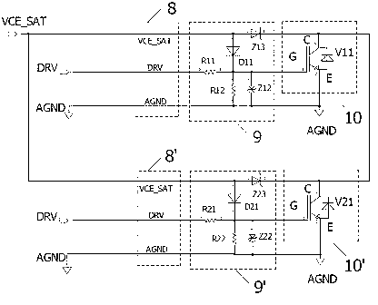
[0016] like figure 1 As shown, the parallel protection circuit includes a soft turn-off module 5 for realizing the safe shutdown of the IGBT module, and the soft turn-off module 5 is respectively connected with the first Vce saturation voltage drop detection module for detecting the short-circuit fault of the IGBT module 6 is connected to the second Vce saturation voltage drop detection module 6' used to detect the short circuit fault of the IGBT module, and the f...


PUM


Abstract

The invention relates to a protection circuit of an IGBT module. The protection circuit comprises an IGBT module soft turn-off protection module, a feedback module formed by an IGBT module Vce saturation voltage drop detection circuit and a feedback optocoupler, a drive circuit connected with the protection circuit, a first drive distribution circuit, a second drive distribution circuit, a first drive wire cable and a second drive wire cable, wherein the drive circuit comprises an IGBT module PWM control signal, a drive isolation module formed by optocouplers, a drive amplification module formed by an audion in a push-pull mode, and a DC / DC power module; the first drive distribution circuit and the second drive distribution circuit are used for being connected with the IGBT module; the first drive wire cable and the second drive wire cable are connected with the drive module, the protection circuit and the distribution circuits. The protection circuit is characterized in that Vce saturation voltage drop detection is respectively carried out on IGBT modules connected in parallel to achieve soft turn-off protection and failure warning of the IGBT modules. The protection circuit can effectively detect shoot-through short circuit faults of any one IGBT module of two or more shunt-wound IGBT modules, safe turn-off of the IGBT modules is achieved through a soft turn-off circuit, and operational reliability of the IGBT modules is improved.

Description

technical field [0001] The invention relates to a protection circuit for parallel connection of IGBT modules, especially for high-power inverters. Background technique [0002] The current high-power inverters on the market usually use the parallel connection of IGBT modules to achieve capacity expansion. This parallel connection technology only requires one driver, and each IGBT module has a driver distribution board. Different IGBT modules and drivers only need to pass through Cable connection, this parallel connection method has the characteristics of simple implementation and low cost, and is widely used in power electronic equipment such as wind energy converters, photovoltaic inverters and frequency converters. [0003] When there are two or more IGBT modules connected in parallel, as shown in the manual figure 2 IGBT modules V11 and V12 are connected in series, IGBT modules V21 and V22 are connected in series, IGBT module V11 and IGBT module V21 are connected in para...

Claims


Application Information

Patent Timeline
IPC IPC(8): H02H7/122
Inventor 吕怀明
Owner ZHEJIANG HAIDE NEW ENERGY
Why Eureka
Try Eureka