Dyeing wastewater heat recovery and antifouling treatment device

A technology of heat energy recovery and antifouling treatment, applied in water/sewage multi-stage treatment, water/sludge/sewage treatment, chemical instruments and methods, etc. and other problems, to achieve the effect of high recycling efficiency, low manufacturing cost and reducing the greenhouse effect

Inactive Publication Date: 2013-10-09
青岛德泰线业有限公司
View PDF6 Cites 3 Cited by
  • Summary
  • Abstract
  • Description
  • Claims
  • Application Information

AI Technical Summary

Problems solved by technology

[0002] At present, in the production process of chemical, textile, printing and dyeing enterprises, a large amount of high-temperature wastewater with a temperature of about 65°C will be produced. These wastewaters contain pollutants and also contain a lot of heat, especially textile printing and dyeing wastewater. , high chroma, and high pollution. Due to the high temperature, some bacteria cannot survive in high-temperature wastewater, and biochemical treatment methods are not easy to adopt. Therefore, only physical and chemical methods can be used for treatment. How to recycle these as much as possible? Heat energy in wastewater is an important task for energy saving and consumption reduction in the textile industry. Although many companies have made great efforts in the treatment of printing and dyeing wastewater, most of them focus on end-of-life treatment. End-of-life treatment refers to the centralized treatment of wastewater generated in various production processes , which not only increases the amount of waste water to be treated, increases the cost of treatment, but also increases the difficulty of treatment. More importantly, all the high temperature is concentrated at the end for treatment, and the heat loss in the water will be very serious, which is very unfavorable for recycling; in addition , the terminal treatment needs to cool the high-temperature printing and dyeing wastewater generated in the production process first, and then needs to be heated again when it is reused. In this process, the waste of heat energy is serious, causing unnecessary loss of energy, and will pollute the environment and affect ecological balance

Method used


Image

  • Dyeing wastewater heat recovery and antifouling treatment device

Examples


Embodiment

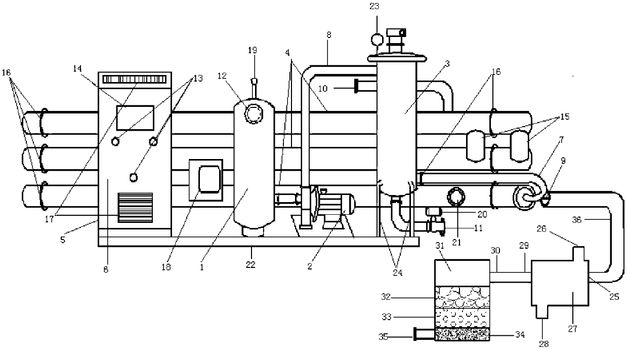
[0009] The main structure of this embodiment includes a vacuum tank 1, a centrifugal pump 2, an automatic filter 3, a heat exchange host 4, a control cabinet 5, a control system 6, a recoil cleaning pipe 7, a sewage inlet 8, a sewage outlet 9, and a clean water inlet. 10. Clean water outlet 11, instrument panel 12, button 13, display screen 14, connecting pipe 15, butt ring buckle 16, heat dissipation window 17, switch box 18, air valve 19, water outlet valve 20, temperature dial 21, base 22, control Valve 23, bracket 24, water inlet 25, filling port 26, regulating tank 27, discharge port 28, water outlet 29, discharge port 30, sedimentation tank 31, coarse-grained layer 32, medium-grained layer 33, fine sand layer 34, Outlet 35 and pipe 36; Control cabinet 5, vacuum tank 1, centrifugal pump 2 and automatic filter 3 are fixed on base 22 from left to right. Centrifugal pump 2 is connected to vacuum tank 1 and the top of vacuum tank 1 An air valve 19 is fixed to extract air from ...


PUM

PropertyMeasurementUnit
thicknessaaaaaaaaaa
thicknessaaaaaaaaaa
thicknessaaaaaaaaaa

Abstract

The invention belongs to the technical field of wastewater heat recovery, and relates to a dyeing wastewater heat recovery and antifouling treatment device. A centrifugal pump is fixedly communicated with a vacuum tank; the top of the vacuum tank is provided with an air valve; the surface of the upper end of the vacuum tank is provided with an instrument board; an automatic filter is fixed to the right end of a base; a water outlet valve is arranged above a clear water outlet; the top of the automatic filter is provided with a control valve; the abutting section of the bottommost end pipeline of the host heat exchanger and a sewage outlet is provided with a thermometer board; the upper surface of a control cabinet is provided with buttons and a display screen; a control system is installed in the control cabinet; a switch box is fixed between two pipelines on the lower part of the host heat exchanger; the right upper end and left lower end of a conditioning tank are respectively provided with a filler port and a discharge port; and a coarse grain layer, a medium grain layer and a fine sand layer are laid in a settling tank. The device has the advantages of reasonable structure, reliable principle, simple technical process, low manufacturing cost, favorable recovery effect and high recovery efficiency, and is simple to operate and environment-friendly.

Description

Technical field: [0001] The invention belongs to the technical field of wastewater thermal energy recovery, and relates to a printing and dyeing wastewater thermal energy recovery and anti-fouling treatment device, which is suitable for textile industry and printing and dyeing wastewater discharge and supplementary production systems, and converts the thermal energy in the wastewater into process water through water-water exchange In order to reduce the temperature of wastewater, heat recycling and protect the environment. Background technique: [0002] At present, in the production process of chemical, textile, printing and dyeing enterprises, a large amount of high-temperature wastewater with a temperature of about 65°C is generated. These wastewater contains a large amount of heat while containing pollutants, especially textile printing and dyeing wastewater, which has high temperature. , High chroma, high pollution, due to the high temperature, some bacteria can not survive i...

Claims


Application Information

Patent Timeline
Patent Type & Authority Applications(China)
IPC IPC(8): C02F9/04
Inventor 邢德茂邢峻玮
Owner 青岛德泰线业有限公司
Why Eureka
Try Eureka