Method for manufacturing backboard used for packaging photovoltaic module

A photovoltaic module packaging and manufacturing method technology, applied in the direction of final product manufacturing, sustainable manufacturing/processing, electrical components, etc., can solve the problems of poor process adaptability and waste, achieve high corrosion rate, reduce the pressure of environmental pollution, save energy material effect

Inactive Publication Date: 2013-10-09
SHUNDE SYSU INST FOR SOLAR ENERGY +1
View PDF4 Cites 0 Cited by
  • Summary
  • Abstract
  • Description
  • Claims
  • Application Information

AI Technical Summary

Problems solved by technology

[0015] In view of the deficiencies in the existing technology, in order to solve the waste of preparing and removing mask materials in the manufacture of photovoltaic module backplanes, alleviate the pressure of environmental pollution, and the poor adaptability of chemical corrosion processes to different metal films, this paper The invention provides a new method of manufacturing a backplane for photovoltaic module packaging, a photovoltaic module backplane manufacturing technology

Method used


Image

  • Method for manufacturing backboard used for packaging photovoltaic module
  • Method for manufacturing backboard used for packaging photovoltaic module

Examples


Embodiment 1

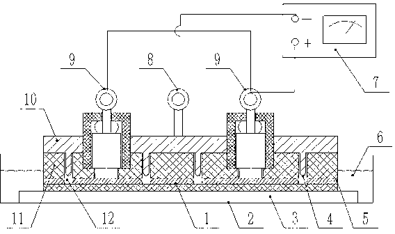
[0032] Such as figure 1 As shown, the method for manufacturing a backplane for photovoltaic module encapsulation in this embodiment includes the following steps: first, compound the thin metal layer 5 and the backplane substrate 14 to form a backplane 1, and the backplane substrate 14 is an insulating material for supporting The thin metal layer 5 is metal aluminum foil. The metal sheet can also consist of two or more layers of different metals, such as aluminum and zinc. The metal thin layer can also be coated with another or several metals on the surface of one layer of metal, such as a layer of zinc and copper coated on the surface of aluminum. The thin metal layer can also be an aluminum alloy.

[0033] Next, forming a connecting circuit on the thin metal layer 5 by etching, specifically includes the following steps: placing the back plate 1 flat on the platform 3 in the corrosion tank 2 with the electrolytic etching solution 6, with the thin metal layer 5 facing upward,...

Embodiment 2

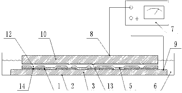
[0036] Such as figure 2 As shown, the method for manufacturing a backplane for photovoltaic module encapsulation in this embodiment includes the following steps: first, compound the thin metal layer 5 with the backplane substrate 14, open an opening at an appropriate position of the backplane substrate 14, and allow the thin metal layer to pass through The opening communicates with the positive pole of the power supply. The metal thin layer 5 is metal aluminum foil. The metal sheet can also consist of two or more layers of different metals, such as aluminum and zinc. The metal thin layer can also be coated with another or several metals on the surface of one layer of metal, such as a layer of zinc and copper coated on the surface of aluminum. The thin metal layer can also be an aluminum alloy.

[0037] Secondly, forming a connecting circuit on the thin metal layer 5 by etching, specifically includes the following steps: placing the backplane substrate 14 compounded with th...


PUM


Abstract

The invention provides a method for manufacturing a backboard used for packaging a photovoltaic module. The method for manufacturing the backboard used for packaging the photovoltaic module solves the problem that mask materials and materials consumed in removing masks in manufacturing a photovoltaic module backboard are wasted and a chemical corrosion technology poorly adapts to the technologies of different metal films. According to the method for manufacturing the backboard used for packaging the photovoltaic module, an electrolytic corrosion method with a template is used for replacing a chemical corrosion method in the prior art, a conducting circuit is formed on a metal thin layer of the backboard in an electrolytic corrosion mode and processes of manufacturing the masks and removing the masks afterwards are removed and thus, materials are saved, cost in manufacturing the backboards is reduced and pressure of environmental pollution is relieved.

Description

technical field [0001] The invention relates to a photovoltaic module manufacturing technology, in particular to a manufacturing technology of a backplane for packaging a single photovoltaic cell into a photovoltaic module. Background technique [0002] With the development of crystalline silicon photovoltaic cell technology, the silicon wafers used to make batteries are becoming thinner and thinner. Thin silicon wafers can reduce the cost of batteries and improve the photoelectric conversion efficiency of batteries, but at the same time, they also bring new challenges to the interconnection, welding and packaging of batteries. There have been many difficulties. For this reason, a packaging method for photovoltaic modules has been developed. In this packaging method, firstly, the positive and negative electrodes of the battery are designed on the back of the battery, and at the same time, the metal thin layer is compounded on the traditional back plate material, and the cor...

Claims


Application Information

Patent Timeline
IPC IPC(8): H01L31/18
CPCY02P70/50
Inventor 李涛勇董娴梁健锋
Owner SHUNDE SYSU INST FOR SOLAR ENERGY
Why Eureka
Try Eureka