Cleaner production system of carbonization furnace group

A clean production and carbonization furnace technology, which is applied in carbonization furnaces, coke ovens, biofuels, etc., can solve the problems of intermittent carbonization furnaces that cannot transfer mass and heat between furnaces, and achieve increased output value and profit, efficient production, and improved thermal efficiency Effect

Inactive Publication Date: 2013-10-23
申买君 +1
View PDF7 Cites 8 Cited by
  • Summary
  • Abstract
  • Description
  • Claims
  • Application Information

AI Technical Summary

Problems solved by technology

[0014] The invention solves the problem that batch carbonization furnaces generally cannot carry out mass transfer and heat transfer between furnaces, and realizes high-efficienc

Method used


Image

  • Cleaner production system of carbonization furnace group
  • Cleaner production system of carbonization furnace group
  • Cleaner production system of carbonization furnace group

Examples


Embodiment Construction

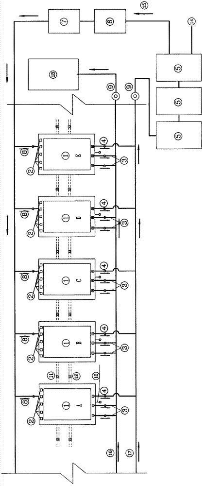
[0028] The pyrolysis furnace designed by this patent belongs to the intermittent production pyrolysis furnace, but works in the mode of furnace group, and its main production process is as follows ( figure 1 ):

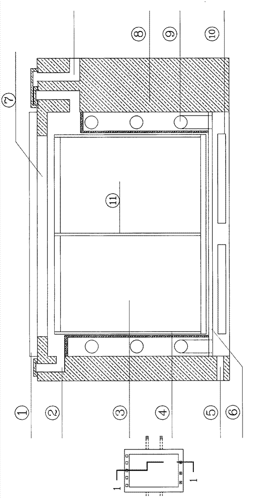
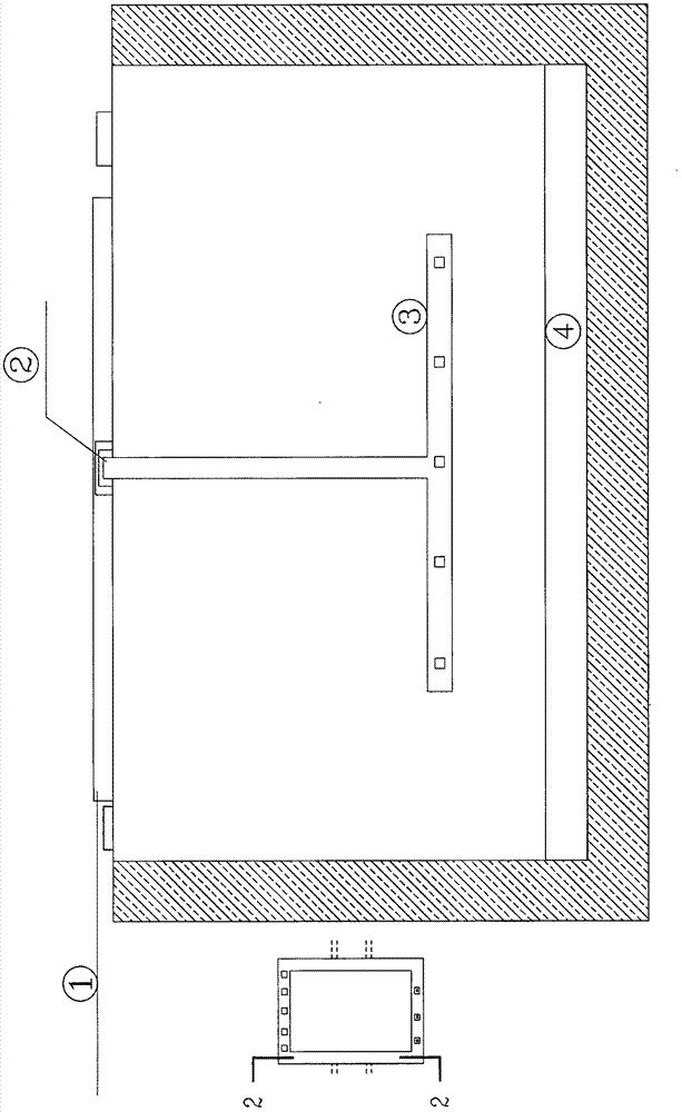
[0029] In the carbonization chamber (ABCD) ① the carbonization cage ( figure 2 ) is filled with biomass, and the air inlet of A carbonization chamber ② ( Figure 5 ) to open (it must be closed when no spontaneous combustion heating is required), and the mass transfer between furnaces heat transfer aisle( image 3 , Figure 4 , Figure 6 , Figure 7 ) connected, close the flue gas and oil gas outlets of the furnace and carbonization chamber ③( Figure 5 ), start the exhaust fan ⑨, ignite the biomass in the carbonization cage or ignite the furnace combustion device, and cover the cover plate of the ABCD carbonization chamber ① ( Figure 8 , Figure 9 ). At the same time, the carbonization furnace in the next 3 (BCD) process closes the air inlet ②, and the c...


PUM


Abstract

The invention discloses a cleaner production system (figure 1) for intermittent carbonization furnaces, which realizes mass transfer and heat transfer between the carbonization furnaces and colony using of the carbonization furnaces. The system adopts the technical scheme that hot air and oil-gas can be transferred to a plurality of following carbonization furnaces (B, C and D) which are not ignited from a current heating (spontaneous combustion or furnace chamber heating) carbonization furnace A through inter-furnace mass transfer and heat transfer passages, so as to progressively realize preheating, drying or preliminary thermal cracking of the carbonization furnaces (B, C and D), which in turn shortens the preparation time of ignition and thermal cracking and facilitates quick temperature reduction after the completion of thermal cracking. The cleaner production system adopting the working mode is conducive to improving the production efficiency, speed and benefits. Moreover, the whole production process is very clean and energy is saved, as the flue gas generated during combustion heating and the oil-gas generated during thermal cracking are processed respectively, the flue gas is directly used for drying biomass materials, the oil-gas enters into a special oil-gas separating tower for processing after being subjected to tunnel cooling (the exchanged heat can be used for geothermal energy of raw materials yards), collected noncondensable gas, namely wood gas, serves as a thermal cracking fuel, and condensed fluid serves as an important by-product of the production.

Description

Technical field [0001] The invention relates to a biomass dry distillation technology belonging to the field of clean energy. It is especially suitable for producing charcoal fuel, wood gas, wood tar and wood vinegar using biomass as raw material. Background technique [0002] The pyrolysis process of biomass can be divided into four stages: [0003] Preheating stage: (room temperature - 100 degrees) to heat the biomass from room temperature, at this stage the biomass basically only changes in temperature. [0004] Dehydration stage: (100-160 degrees) At this stage, the biomass only undergoes physical changes, mainly losing water. [0005] Thermal cracking stage: (160-500 degrees) In this stage, biomass is thermally decomposed under anoxic conditions. As the temperature continues to rise, various volatiles are correspondingly precipitated, and most of the mass loss of raw materials occurs. [0006] Calcination stage: (>500 degrees) The decomposition that occurs at this...

Claims


Application Information

Patent Timeline
IPC IPC(8): C10B1/00C10B53/02
CPCY02E50/14Y02E50/10
Inventor 申买君向礼光
Owner 申买君
Why Eureka
Try Eureka