Plasma cladding gradient wearing layer and its preparation technology

A technology of plasma cladding and preparation process, applied in the direction of metal material coating process, coating, etc., can solve problems such as peeling, stress concentration, cracks, etc., and achieve the effect of preventing layer peeling, low wear amount, and improved impact resistance.

Active Publication Date: 2013-10-23
CHINA UNIV OF MINING & TECH
View PDF4 Cites 25 Cited by
  • Summary
  • Abstract
  • Description
  • Claims
  • Application Information

AI Technical Summary

Problems solved by technology

At present, some scholars have used plasma cladding technology to obtain a fine, dense, uniform, pore-free, and crack-free cladding layer on the surface of the workpiece;

Method used


Image

  • Plasma cladding gradient wearing layer and its preparation technology
  • Plasma cladding gradient wearing layer and its preparation technology
  • Plasma cladding gradient wearing layer and its preparation technology

Examples


Embodiment 1

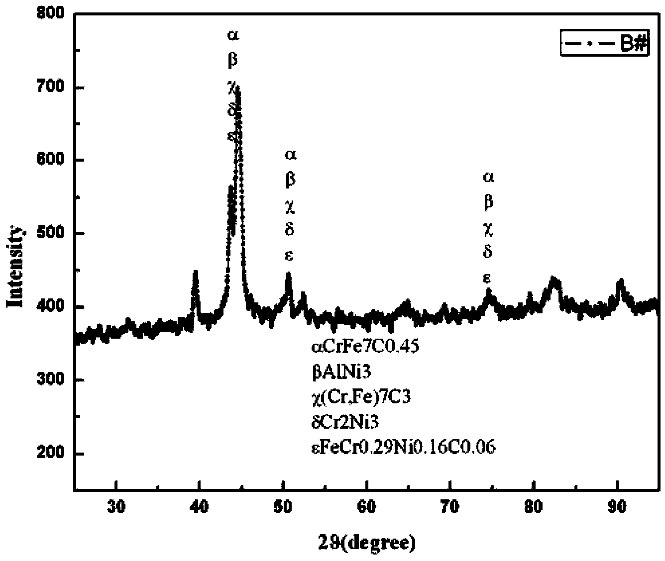
[0030] The composition (weight %) of the cladding layer in the plasma cladding gradient wear-resistant layer is as follows:

[0031] Si: 2%, Mn: 2%, Al: 1%, Mo: 0.5%, Ni: 4%, Cr 3 C 2 : 30%, the balance is Fe.

[0032] The composition (weight %) of the outer cladding layer of the plasma cladding gradient wear-resistant layer is as follows:

[0033] Si: 2%, Mn: 2%, Al: 1%, Mo: 0.5%, Ni: 4%, Cr 3 C 2 : 40%, the balance is Fe.

[0034] The gradient wear-resistant layer is prepared as follows:

[0035] First, in order to ensure the effect of plasma cladding, trichlorethylene was used to remove impurities and oil stains on the surface of the substrate (#45 steel), and the substrate was preheated at 140°C. The component powders are screened by sieving method and microscopic observation method. The particle size distribution is between 80 and 100 mesh. Put it into a drying oven for drying, the temperature is controlled at 150°C, and the powder is turned during the drying proce...

Embodiment 2

[0037] The composition (weight %) of the cladding layer in the plasma cladding gradient wear-resistant layer is as follows:

[0038] Si: 2%, Mn: 2%, Al: 1%, Mo: 0.5%, Ni: 4%, Cr3 C 2 : 30%, the balance is Fe.

[0039] The composition (weight %) of the outer cladding layer of the plasma cladding gradient wear-resistant layer is as follows:

[0040] Si: 2%, Mn: 2%, Al: 1%, Mo: 0.5%, Ni: 4%, Cr 3 C 2 : 50%, the balance is Fe.

[0041] The process parameters for preparing the inner cladding layer using PLC plasma spray welding equipment are as follows:

[0042] Plasma gas: argon, working current: 120A, working voltage: 17.5V, protective gas flow: 1.2m 3 / h, power gas flow: 0.8m 3 / h, distance from nozzle to surface: 10mm, scanning speed: 190mm / min.

[0043] The process parameters for preparing the outer cladding layer using PLC plasma spray welding equipment are as follows:

[0044] Plasma gas: argon, working current: 127A, working voltage: 16.9V, protective gas flow: 1.2m...


PUM

PropertyMeasurementUnit
Hardnessaaaaaaaaaa

Abstract

A plasma cladding gradient wearing layer and its preparation technology belong to the field of a wearing layer preparation technology. By a plasma cladding technology, inner cladding layer and outer cladding layer alloy powders are adopted to prepare a gradient wear resistant cladding layer on the surface of a matrix so as to obtain an abrasion-resistant corrosion-resistant impact-resistant sliding shoe wearing layer of a coal cutter. The preparation technology comprises the following steps: (1) pretreatment of a substrate before plasma cladding; (2) pretreatment of iron-based metallurgy powder before plasma cladding; (3) preparation of an inner cladding layer; and (4) preparation of an outer cladding layer. According to the plasma cladding gradient wearing layer, gradient change of a microstructure from the outer cladding layer surface to a fusion line is realized. The gradient cladding layer has incomparable advantages compared with a single cladding layer, and is the best performance matching between the ceramic cladding layer and a metallurgy matrix. A distribution curve of hardness from the outer cladding layer to a heat effect area of the matrix slowly declines like a ladder; surface hardness is raised; friction coefficient variation trend is mild; wearing capacity is low; and corrosion resistance and impact resistance are greatly raised.

Description

technical field [0001] The invention relates to a wear-resistant layer and its preparation process, in particular to a plasma cladding gradient wear-resistant layer and its preparation process. Background technique [0002] Sliding shoe is the supporting part of the coal mining machine, which is divided into supporting sliding shoe and guiding sliding shoe. The role of the supporting shoe is mainly to support, and the guiding shoe not only plays a supporting role, but also enables the shearer to advance along the track, and offsets the lateral force of the coal wall. Sliding shoes not only have to bear the weight of the shearer, but also have to bear a lot of frictional resistance. Therefore, the sliding shoe is an important part on the base of the shearer that bears low speed and heavy load and requires extremely high wear resistance. In view of the harsh working environment and complex force of the shearer, and the increasing installed power and weight of the shearer, th...

Claims


Application Information

Patent Timeline
IPC IPC(8): C23C24/10C22C38/58C22C38/44C22C32/00C22C30/00C22C29/06
Inventor 张德坤王崧全殷燕
Owner CHINA UNIV OF MINING & TECH
Why Eureka
Try Eureka