Two-stage expansion power generation device and method for recovering liquefied natural gas cold energy

A technology of liquefied natural gas and two-stage expansion, which is applied in the direction of steam engine devices, machines/engines, mechanical equipment, etc., can solve the problems of low demand for direct cooling, complex process flow, and low efficiency, and achieve less equipment, simple process, and low cost. low effect

Inactive Publication Date: 2013-10-23
NORTH CHINA INST OF SCI & TECH
View PDF5 Cites 33 Cited by
  • Summary
  • Abstract
  • Description
  • Claims
  • Application Information

AI Technical Summary

Problems solved by technology

This technical solution is a cascaded cold energy utilization scheme of LNG cold energy. Only part of the LNG cold energy is used to generate electricity. This part of the electricity uses butane as the working medium, and uses a butane Rankine cycle to convert the cold energy of LNG. For electric energy, the single-stage butane Rankine power cycle is not efficient in converting cold energy into electric energy. This technical solution is suitable for direct use of cold places such as cold energy service companies, cold storage, ice rinks, and air conditioners around the LNG station. It is more suitable for the situation of large cooling capacity, but many LNG receiving stations have no direct cooling demand or low direct cooling demand, and it is necessary to convert cooling energy into electrical energy as much as possible. In this case, the efficiency of this technical solution is not high.
[0006] (4) if Figure 4 As shown, the LNG cold energy multi-stage recycling system suitable for ships, the system is suitable for the ship's LNG cold energy multi-stage utilization system, the system includes: LNG storage tank, booster pump, first condenser, second condenser The LNG vaporization and heating expansio

Method used


Image

  • Two-stage expansion power generation device and method for recovering liquefied natural gas cold energy
  • Two-stage expansion power generation device and method for recovering liquefied natural gas cold energy
  • Two-stage expansion power generation device and method for recovering liquefied natural gas cold energy

Examples


Embodiment 1

[0028] like Figure 5 As shown, the two-stage expansion power generation device for recovering the cold energy of liquefied natural gas of the present invention includes an LNG pump 11, a plate-fin multi-stream low-temperature heat exchanger 12, first to fourth heat exchangers 13-16, a first stage turboexpander 17 , first generator 18 , second stage turboexpander 19 , second generator 20 , first working medium pump 21 and second working medium pump 22 .

[0029] One end of the LNG pump 11 is connected to the LNG supply source (not shown in the figure), and the other end of the LNG pump 11 is connected to the inlet of the first flow channel (a) of the plate-fin multi-stream cryogenic heat exchanger 12, the plate-fin type The outlet of the first flow channel (a) of the multi-stream cryogenic heat exchanger 12 is connected to the inlet of the first heat exchanger 13, and the outlet of the first heat exchanger 13 is connected to the export pipeline NG.

[0030] The output work of...

Embodiment 2

[0038] like Image 6 As shown, according to whether there is suitable industrial waste heat available on site, the industrial waste heat can be used to improve power generation efficiency under possible conditions. The structure of this embodiment is exactly the same as that of embodiment 1, the only difference is that the The fourth heat exchanger 16 can exchange heat with industrial waste heat. Wherein, the working fluid is heated to 40°C-90°C by using industrial waste heat, preferably 50°C-80°C.

Embodiment 3

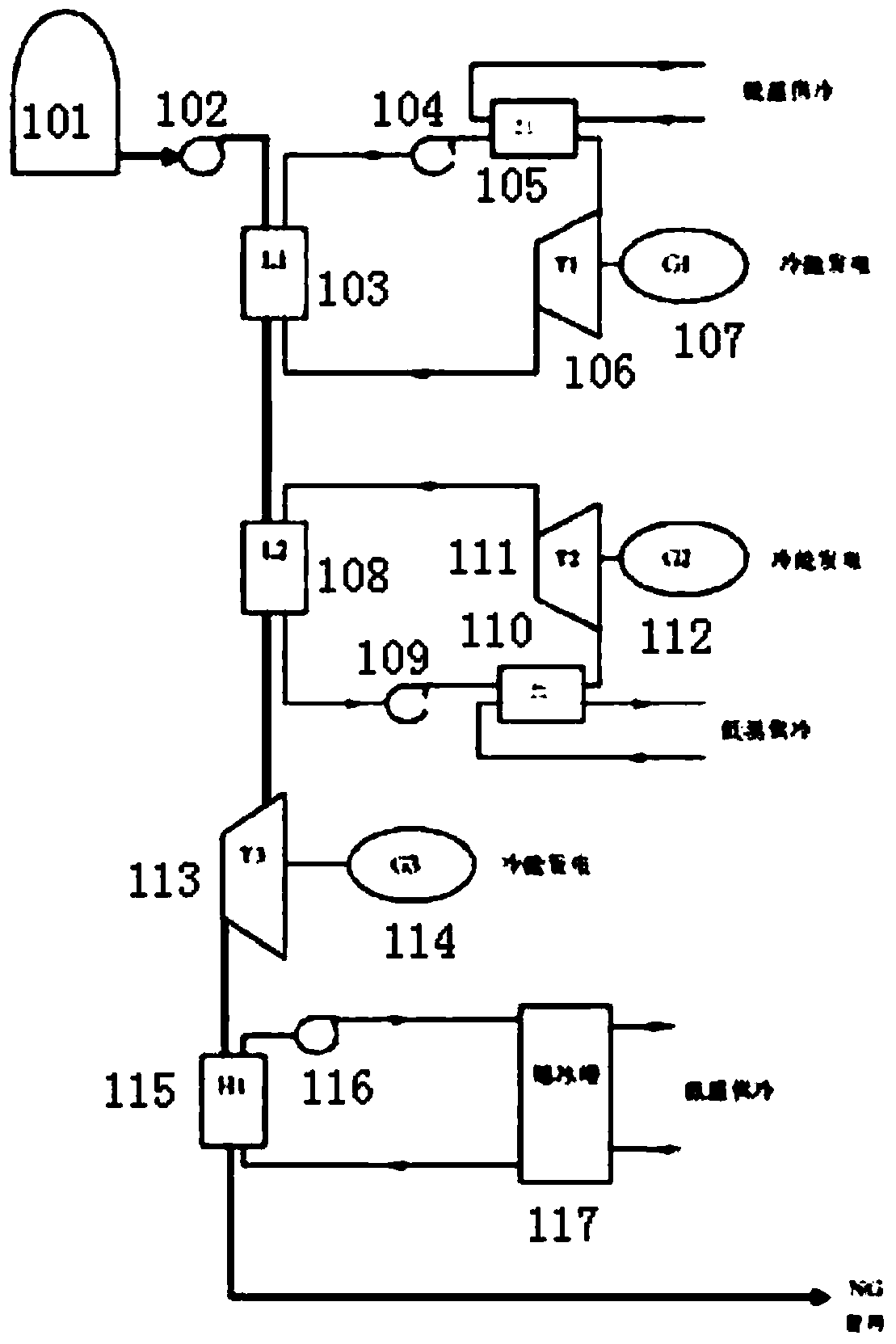
[0040] like Figure 7 As shown, the structure of this embodiment is basically the same as that of Embodiment 1, the difference is that: a fifth heat exchanger 23 and a natural gas expander 24 are also included; the outlet of the first heat exchanger 13 in Embodiment 1 is connected The inlet of the fifth heat exchanger 23 and the outlet of the fifth heat exchanger 23 are connected to the inlet of the natural gas expander 24, and the outlet of the natural gas expander 24 is connected to the export pipeline NG.

[0041] After the LNG passes through the LNG pump 11 to increase the pressure to 8MPa-15MPa, it enters the first channel of the plate-fin multi-stream low-temperature heat exchanger 12 to be vaporized and heated up. After heat exchange, the LNG is first exchanged with the refrigerant in the first heat exchanger 13. The heat is then exchanged with the external environment through the fifth heat exchanger 23, and sent to the natural gas turbo expander 24 after the heat exch...


PUM


Abstract

The invention relates to a two-stage expansion power generation device and method for recovering liquefied natural gas cold energy. LNG enters a first runner of a multi-stream cryogenic heat exchanger for vaporization and temperature rise after passing through an LNG pump for pressure rise; high-pressure working medium gas outputs electric power after entering a first-stage turbine expander for expansion, the working medium gas is divided into two parts, the first part enters a second runner of a plate-fin multi-stream cryogenic heat exchanger to absorb the LNG cold energy and become liquid through condensation, and then a pump is used for pressurization; the second part enters a second-stage turbine expander for expansion after passing through a second heat exchanger, enters a third runner of the plate-fin multi-stream cryogenic heat exchanger to become liquid through condensation, enters a fourth runner after being pressurized through the pump, converges with the first part of the working medium gas, conducts heat exchange with a refrigerant after the convergence, and then returns to an inlet of the first-stage turbine expander after conducting heat exchange with the environment and/or absorbing industrial waste heat to finish the circulation. Power output by the first-stage turbine expander and power output by the second-stage turbine expander are both used for generating the electric power. According to the two-stage expansion power generation device and method for recovering the liquefied natural gas cold energy, ethylene or ethane is used as the working medium, the LNG cold energy and the waste heat are recovered for power generation, and the two-stage expansion power generation device and method can be widely applied to power generation through utilization of the liquefied natural gas cold energy.

Description

technical field [0001] The invention relates to a power generation device and method, in particular to a two-stage expansion power generation device and method that uses ethylene or ethane as a working medium and can recover the cold energy of liquefied natural gas or utilize the cold energy of LNG and industrial waste heat to generate electricity. Background technique [0002] Liquefied natural gas (LNG) is a clean, efficient and large-scale fossil energy obtained by condensing natural gas into liquid at low temperature. Although LNG is in a liquid state during storage and transportation, it needs to be vaporized into a gas when it is used. In this process, a large amount of high-quality low-temperature refrigeration will be released. If it is not recycled, it will not only cause waste but also cause serious damage. "Cold Pollution". LNG cold energy utilization technologies include LNG power generation, air separation, cold storage cold source, seawater desalination, light...

Claims


Application Information

Patent Timeline
IPC IPC(8): F01K25/10F01K23/18
Inventor 朱鸿梅孙恒牛永胜刘宏伟李琼
Owner NORTH CHINA INST OF SCI & TECH
Why Eureka
Try Eureka