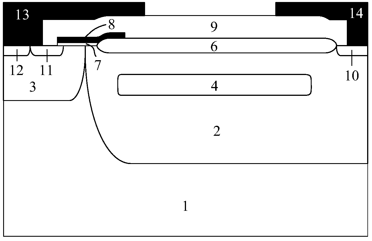
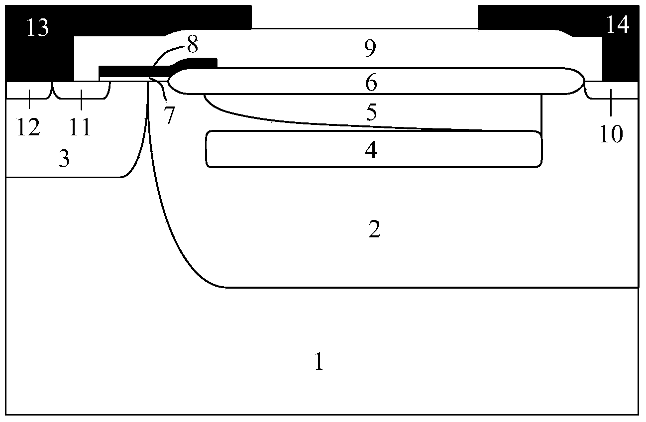
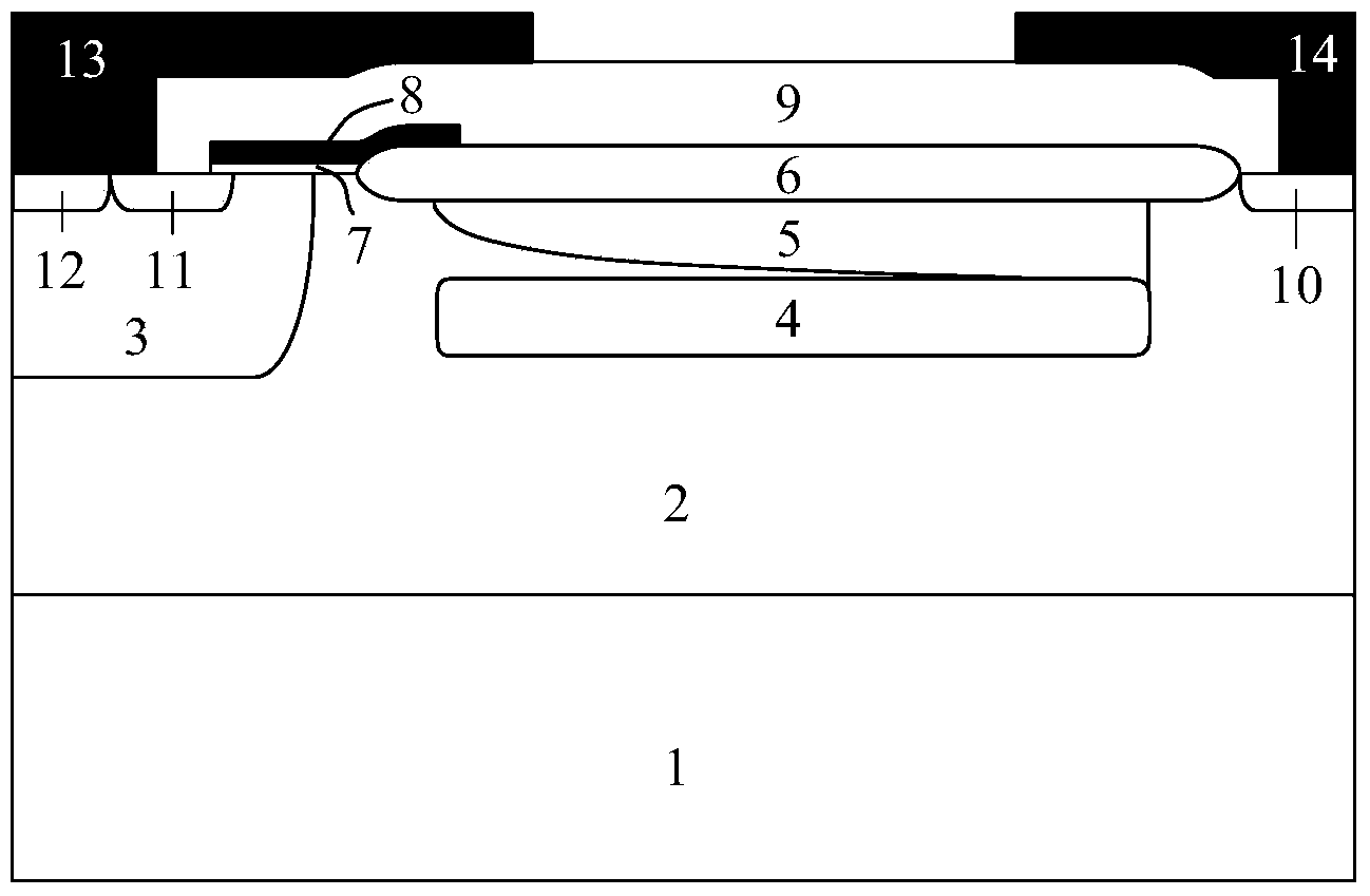
Laterally high-voltage MOSFET and manufacturing method thereof
A technology of lateral high voltage and manufacturing method, which is applied in semiconductor/solid-state device manufacturing, electrical components, circuits, etc., can solve the problems of rising on-resistance, etc., and achieve the goals of reducing electric field peak value, small on-resistance, and improving breakdown voltage Effect
- Summary
- Abstract
- Description
- Claims
- Application Information
AI Technical Summary
Problems solved by technology
Method used
Image
Examples
Embodiment 1
[0061] The adopted process of this example is that the second conductivity type semiconductor heavily doped layer 5 has a plurality of smaller ion implantation windows, the size of the small windows is the same, and the spacing of the windows is different, along with the second conductivity type semiconductor drain region 10 approaching, the injection window gradually decreases, as Figure 4 shown. Figure 5 It is a cross-sectional view of the device structure after implantation of semiconductor impurities of the second conductivity type. In the figure, the semiconductor impurities 15 of the second conductivity type are diffused by annealing to form a heavily doped layer 5 of the semiconductor of the second conductivity type with a linear doping distribution, such as Figure 6 shown. At the same time, the field oxide layer 6 is formed before the ion implantation process of the first conductivity type semiconductor field drop layer 4 , the field oxide layer 6 is formed first, ...
Embodiment 2
[0063] The process used in this example is to first form the first conductive type semiconductor field drop layer 4 and the second conductive type semiconductor heavily doped layer 5, and then form the field oxide layer 6, the first conductive type semiconductor field drop layer 4, The second conductivity type semiconductor heavily doped layer 5 and the field oxide layer 6 are annealed together. At the same time, the second conductivity type semiconductor heavily doped layer 5 has a plurality of smaller ion implantation windows, the size of the implantation windows is the same, the spacing is different, and the window spacing gradually decreases as it approaches the second conductivity type semiconductor drain region 10, Such as Figure 7 shown. Figure 8 It is a cross-sectional view of the device structure after implantation of semiconductor impurities of the second conductivity type. In the figure, the semiconductor impurities 15 of the second conductivity type are diffused...
Embodiment 3
[0065] The adopted process of this example is that the second conductivity type semiconductor heavily doped layer 5 has a plurality of smaller ion implantation windows, the spacing of the small windows is the same, and the size of the windows is different, as the second conductivity type semiconductor drain region 10 approaches gradually decrease, as Figure 10 shown. Figure 11 It is a cross-sectional view of the device structure after implantation of semiconductor impurities of the second conductivity type. In the figure, the semiconductor impurities 15 of the second conductivity type are diffused by annealing to form a heavily doped layer 5 of the semiconductor of the second conductivity type with a linear doping distribution, such as Figure 12 shown. At the same time, the field oxide layer 6 is formed before the ion implantation process of the first conductivity type semiconductor field drop layer 4 , the field oxide layer 6 is formed first, and the annealing process of ...
PUM
 Abstract
Description
Claims
Application Information
 - R&D
- Intellectual Property
- Life Sciences
- Materials
- Tech Scout
- Unparalleled Data Quality
- Higher Quality Content
- 60% Fewer Hallucinations
Browse by: Latest US Patents, China's latest patents, Technical Efficacy Thesaurus, Application Domain, Technology Topic, Popular Technical Reports.
© 2025 PatSnap. All rights reserved.Legal|Privacy policy|Modern Slavery Act Transparency Statement|Sitemap|About US| Contact US: help@patsnap.com


