A light-gathering cavity for solid-state lasers

A technology of solid-state lasers and concentrating cavities, which is applied to the structure/shape of optical resonators, can solve the problems of poor high temperature resistance, poor impact and vibration resistance of the diffuse reflection layer, and low reflectivity of the diffuse reflection layer. Strong shock and vibration resistance, high temperature resistance, and small thickness

Active Publication Date: 2016-08-10
BEIJING AERONAUTICAL MFG TECH RES INST
View PDF5 Cites 0 Cited by
  • Summary
  • Abstract
  • Description
  • Claims
  • Application Information

AI Technical Summary

Problems solved by technology

The disadvantages are: first, the reflectivity of the diffuse reflection layer is low, usually the thickness must be greater than 4mm, resulting in a relatively large volume of the light-gathering cavity; second, the high temperature resistance of the diffuse reflection layer is poor, resulting in a decrease in reflectivity and uneven reflection ; Third, the structure is complex and difficult to process; Fourth, the ability to withstand shock and vibration is poor

Method used


Image

  • A light-gathering cavity for solid-state lasers

Examples


Embodiment 1

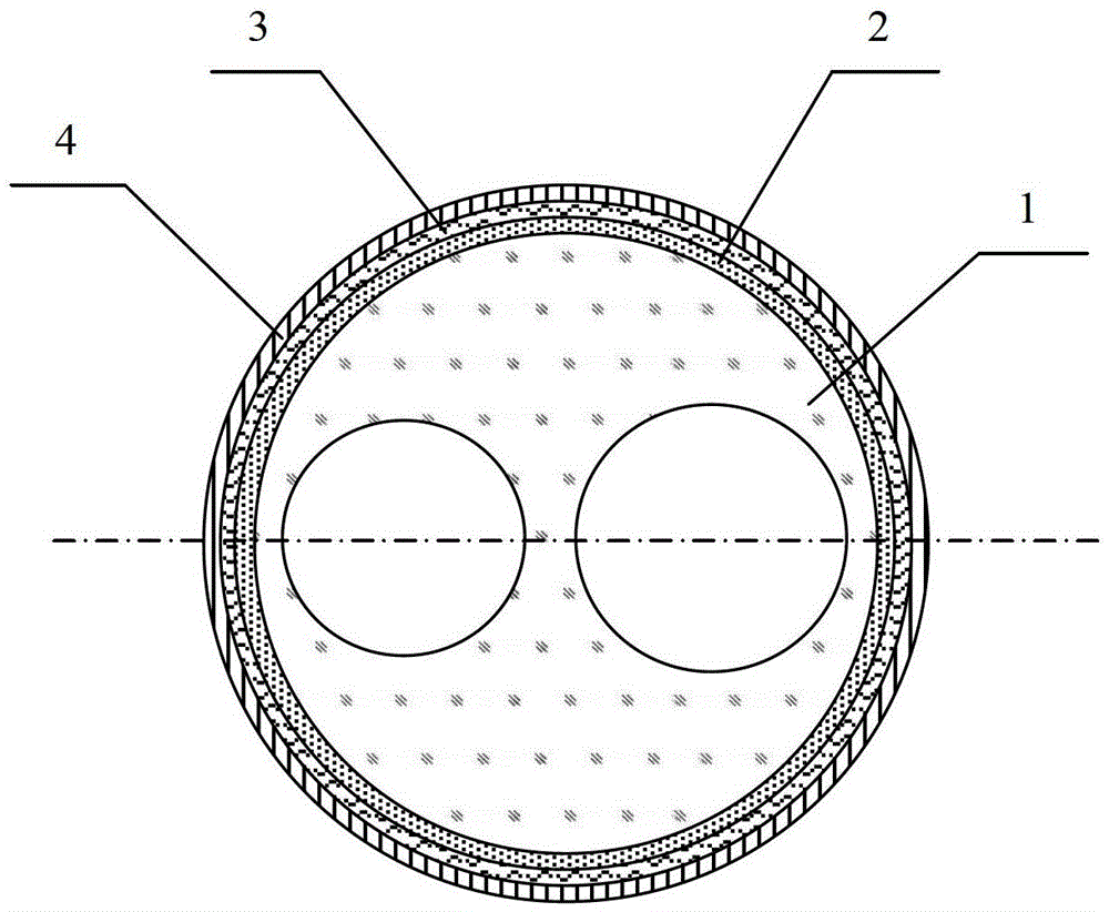
[0013] The shape of the quartz rod is cylindrical, and the diffuse reflection coating is sprayed with 0.3mm thick BaSO 4 powder, followed by a layer of SiO 2 The coating has a thickness of 50 μm; the metal reflective layer is made of silver and has a thickness of 0.2 mm.

[0014] The laser rod adopts Nd:YAG, diameter Ф15mm, and the pump lamp adopts pulsed xenon lamp. Gain measurement results show that for the pump cavity with this structure, the gain non-uniformity in the laser rod cross-section does not exceed 5%, and the calculation of the amplifier shows that this gain non-uniformity can obtain satisfactory radiation intensity uniformity at the output of the amplifier sex. It adopts the working mode of one-stage local oscillator and four-stage amplification, among which the four-stage amplification is manufactured by the light-collecting cavity, and obtains 100Hz, 3J, and pulse width of 10ns high peak power laser output, and the beam quality is better than 5mm*mrad. Due ...

Embodiment 2

[0016] The shape of the quartz rod is still cylindrical, and the diffuse reflection coating is sprayed with 0.15mm thick BaSO 4 powder, followed by a layer of SiO 2 The coating has a thickness of 100 μm; the metal reflective layer is made of silver material and has a thickness of 0.3 mm.

[0017] It adopts the working mode of one-stage local oscillator and four-stage amplification, among which the four-stage amplification is made of the light-collecting cavity, and obtains 5Hz, 6J, pulse width 10ns high peak power laser output, and the beam quality is better than 5mm*mrad. Due to the low repetition rate and high single pulse energy of this laser, the thickness of the diffuse reflection coating is appropriately reduced and the thickness of the metal reflection layer is increased. The laser is used in laser surface impact strengthening processing equipment, and has the advantages of small size, light weight, stability and reliability, and easy operation.


PUM


Abstract

The invention provides a laser-gathering cavity for a solid laser, belongs to the technical field of solid lasers, and relates to improvement on a laser-gathering cavity of an existing high-power lamp pumped solid laser. The laser-gathering cavity comprises a quartz rod (1), and a pumping lamp installation hole and a laser rod installation hole are formed in the inner portion of the quartz rod (1). The laser-gathering cavity is characterized in that a laser-gathering reflection coating is plated on the outer surface, except two end faces, of the quartz rod (1), and the laser-gathering reflection coating is divided into three layers which contain a diffuse reflection coating body (2), a silicon dioxide film (3) and a metallic reflection film (4) from inside to outside. According to the laser-gathering cavity for the solid laser, the reflection coating is high in reflectivity and small in thickness, so that the size of the laser-gathering cavity is reduced greatly; the diffuse reflection coating body is strong in high-temperature resistance and even in reflection; the laser-gathering cavity is simple in structure, convenient to process and strong in impact vibration resistance.

Description

technical field [0001] The invention belongs to the field of solid-state laser technology, and relates to the improvement of the light-gathering cavity of the existing high-power lamp-pumped solid-state laser. Background technique [0002] For high-power solid-state lasers, the higher the pump power, the greater the heat accumulation in the working substance, and the thermal lens, thermally induced birefringence and thermal focusing caused by the uneven temperature change of the working substance will distort the passing beam, resulting in The quality of the light beam decreases, and in severe cases, it will cause damage to the working substance or other optical components, resulting in the collapse of the system. Therefore, there is a contradiction between high output energy and high beam quality. On the one hand, high output energy will cause a decrease in beam quality; on the other hand, high output energy must be based on high beam quality. The method to solve this cont...

Claims


Application Information

Patent Timeline
Patent Type & Authority Patents(China)
IPC IPC(8): H01S3/08
Inventor 胡文华任士龙李忠建
Owner BEIJING AERONAUTICAL MFG TECH RES INST
Why Eureka
Try Eureka