Milling device and method for inner-hole oil grooves

A technology of milling processing and oil grooves, which is applied in the field of milling processing devices for inner hole oil grooves and processing devices for inner hole grooves, can solve the problems of scattered structure layout, no obvious advantage in efficiency, poor dimensional accuracy of oil groove processing, etc., and achieve high smoothness, Achieve a qualitative leap in equipment processing efficiency and high depth precision

Inactive Publication Date: 2013-12-04
CHANGSHU HUAWEI TRACK
View PDF6 Cites 10 Cited by
  • Summary
  • Abstract
  • Description
  • Claims
  • Application Information

AI Technical Summary

Problems solved by technology

It has many disadvantages, such as poor machining dimensional accuracy and poor finish of the oil tank, large equipment processing vibrations lead to rapid equipment loss; the shape of the processing oil tank is single, one person and one machine are required to operate, and the production efficiency is low;
[0007] 2) Some of the oil tanks are processed by CNC lathe programming and EDM, and these two processing methods have relatively large limitations;
[0008] 3) Partially introduce power head processing, and adopt the principle of CNC cutting to realize various oil groove processing, but the structure layout is scattered, and it is difficult to realize multi-station on one machine, and the milling cutter is driven by a belt pulley, it is difficult to achieve high-strength cutting , and it is not easy to realize multi-station processing, compared with the traditional lathe broaching machine, there is no obvious advantage in efficiency

Method used


Image

  • Milling device and method for inner-hole oil grooves
  • Milling device and method for inner-hole oil grooves
  • Milling device and method for inner-hole oil grooves

Examples


Embodiment Construction

[0032] The following will clearly and completely describe the technical solutions in the embodiments of the present invention with reference to the accompanying drawings in the embodiments of the present invention. Obviously, the described embodiments are only some, not all, embodiments of the present invention. Based on the embodiments of the present invention, all other embodiments obtained by persons of ordinary skill in the art without creative efforts fall within the protection scope of the present invention.

[0033] It should be noted that, in the case of no conflict, the embodiments of the present invention and the features in the embodiments can be combined with each other.

[0034] Embodiments of the present invention will be specifically explained below in conjunction with the accompanying drawings.

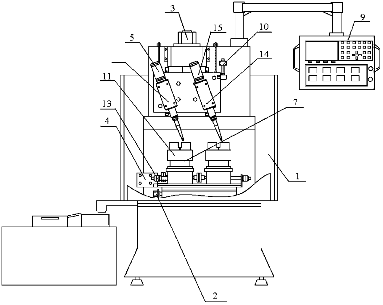
[0035] Such as figure 1 A milling device for an inner hole oil groove according to an embodiment of the present invention shown in , includes a horizontal feed mechan...


PUM


Abstract

The invention discloses a milling device and a milling method for inner-hole oil grooves and belongs to the field of machine manufacturing. The milling device comprises a horizontal feeding mechanism, a vertical feeding mechanism, a first circumferential feeding mechanism, a second circumferential feeding mechanism, a first cutting mechanism and a clamping mechanism, which are arranged on a frame, wherein the first circumferential feeding mechanism rotates to drive the clamping mechanism; the horizontal feeding mechanism drives the first circumferential feeding mechanism and the clamping mechanism to move horizontally; the second circumferential feeding mechanism rotates to drive the first cutting mechanism; the vertical feeding mechanism drives the second circumferential feeding mechanism and the first cutting mechanism to move vertically; the first cutting mechanism and the clamping mechanism cooperate with each other and are arranged from the top down in the vertical direction. The technical scheme provided by the invention realizes a double-shaft and double-rotating oil groove processing way through combination of double circumferential feeding, vertical feeding and depth-direction feeding; the structure is compact; the production efficiency of inner-hole oil grooves can be improved greatly.

Description

[0001] The invention belongs to the field of mechanical equipment manufacturing, and relates to a processing device for an inner hole groove, in particular to a milling processing device and method for an inner hole oil groove. Background technique [0002] The oil tank structure is used as the key structure for storing lubricating oil in sleeves and pipe parts, especially in the shaft sleeves of key rotating parts of construction machinery, such as for the rotating parts of excavator working devices. There are various structures of oil grooves, for example, the inner holes of some shaft sleeve products need to process oil grooves of various shapes such as annular grooves and straight grooves. [0003] For the processing of the above structure, there is no general-purpose special equipment on the market at present. Most of the plans are to modify the special machine on the ordinary car, but the precision control and efficiency of the oil tank have not been properly solved. [...

Claims


Application Information

Patent Timeline
Patent Type & Authority Applications(China)
IPC IPC(8): B23C3/28B23Q5/28
Inventor 罗伟吴凯康思军
Owner CHANGSHU HUAWEI TRACK
Why Eureka
Try Eureka