Synchronous pulley drilling machine used for manufacturing synchronous pulleys

A technology of synchronous pulley and drilling machine, which is applied in the direction of boring/drilling, drilling/drilling equipment, parts of boring machine/drilling machine, etc. It can solve the problems of high waste products and increase the production cost of synchronous pulleys, and achieve The overall structure is simple, the cost is low, and the effect of avoiding damage

Inactive Publication Date: 2013-12-11
CHENGDU SILVERTECH TIMING PULLEYS MFG
View PDF0 Cites 10 Cited by
  • Summary
  • Abstract
  • Description
  • Claims
  • Application Information

AI Technical Summary

Problems solved by technology

During the manufacturing process of the synchronous pulley, it needs to be drilled. Nowadays, the synchronous pulley cannot be positioned well when drilling

Method used


Image

  • Synchronous pulley drilling machine used for manufacturing synchronous pulleys

Examples


Embodiment

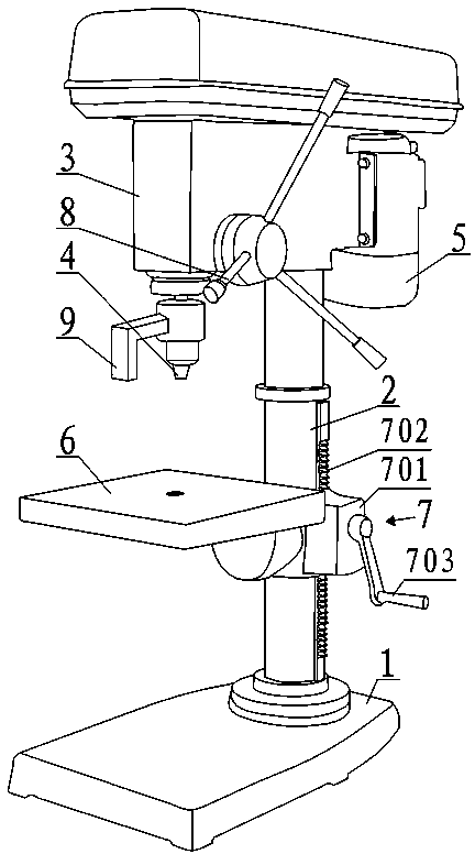
[0018] Such as figure 1 As shown, the drilling machine for synchronous pulleys when producing synchronous pulleys includes a base 1, a column 2, a positioning seat 3, a drill bit 4, a workbench 6 and a drive motor 5, wherein the column 2 is arranged on the base 1, Both the positioning seat 3 and the worktable 6 are connected to the column 2, and the workbench 6 is located below the positioning seat 3. The positioning seat 3 is provided with a drill bit lifting mechanism to control the rise or fall of the drill bit 4. The upper end of the drill bit 4 is connected with the drill bit lifting mechanism. The drill bit 4 is located between the positioning seat 3 and the workbench 6. The synchronous pulley positioning hole, the drive motor 5 is fixed on the positioning seat 3 and is used to drive the drill bit 4 to rotate.

[0019] The drill lifting mechanism comprises the first gear, the first handle 8, the first rotating shaft arranged horizontally, and the first tooth bar arrange...


PUM


Abstract

The invention discloses a synchronous pulley drilling machine used for manufacturing synchronous pulleys. The synchronous pulley drilling machine comprises a base, a stand column, a locating base, a drill bit, a workbench, a limiting mechanism and a driving motor driving the drill bit to rotate. The stand column is arranged on the base, both the locating base and the workbench are connected to the stand column, the workbench is located below the locating base, a drill bit lifting mechanism for controlling the drill bit to lift or descend is arranged on the locating base, a connecting base connected with the drill bit lifting mechanism is arranged at the upper end of the drill bit, the drill bit is located between the locating base and the workbench, and a synchronous pulley locating hole is formed in the portion, right facing toward the drill bit, of the workbench. The limiting mechanism comprises a transverse connecting plate and a longitudinal limiting plate, the longitudinal limiting plate is arranged above the workbench and parallel with the drill bit, and the two ends of the transverse connecting plate are connected with the longitudinal limiting plate and the connecting base respectively. When the synchronous pulley drilling machine is used, the synchronous pulleys can be drilled after being located, the rate of finished products of the synchronous pulleys can be promoted, and cost is saved. The drilling depth can be limited through the limiting mechanism, and thus the synchronous pulleys can be prevented from being damaged.

Description

technical field [0001] The invention relates to a mechanical processing tool, in particular to a drilling machine for synchronous pulleys when producing synchronous pulleys. Background technique [0002] Synchronous belt drive, also known as meshing belt drive, is a meshing transmission composed of a synchronous belt and a synchronous pulley, and its motion and power are transmitted through the meshing of the belt teeth and the gear teeth. Compared with the friction belt drive, the synchronous belt drive transmits motion and power by meshing with the pulley, and there is no relative slip between the belt and the pulley, which can ensure an accurate transmission ratio. Therefore, the synchronous belt drive is widely used in machinery in the transmission. As an important component in synchronous belt transmission, synchronous pulleys are generally made of steel, aluminum alloy, cast iron, brass and other materials. In the manufacturing process of the synchronous pulley, it ...

Claims


Application Information

Patent Timeline
IPC IPC(8): B23B41/00B23B47/00B23B47/26B23Q1/25B23Q5/10B23Q3/18
Inventor 刘选明刘黎竞
Owner CHENGDU SILVERTECH TIMING PULLEYS MFG
Why Eureka
Try Eureka