Optical network-based automobile electric system

A technology for electrical systems and optical fiber networks, applied in vehicle components, circuits or fluid pipelines, transportation and packaging, etc., can solve problems such as corrosion, scalability to be improved, high cost, etc., to achieve strong application and market prospects, component upgrades Simple and easy, avoids the effect of electrical short circuit

Active Publication Date: 2013-12-11
JIANGSU TONGMING GAOKE AUTOMOTIVE ELECTRICAL EQUIP
View PDF6 Cites 11 Cited by
  • Summary
  • Abstract
  • Description
  • Claims
  • Application Information

AI Technical Summary

Problems solved by technology

[0003] However, with the rapid development of the automobile industry, the traditional automotive electrical system with wiring harnesses as the main connection method has the following shortcomings in actual operation, mainly in the following aspects: (1) The wiring harness is becoming more and more complicated, and it is difficult to achieve information sharing; With the increase in the number of data communications between electronic control units, the high-speed data transmission rate becomes very important, and the transmission rate of ordinary wire harnesses can no longer meet the high-speed data transmission
(2) Metal wires are easy to oxidize and corrode, which leads to an increase in line impedance, affects the correct transmission or connection of electrical signals, and easily leads to short circuit or spontaneous combustion, thus posing safety hazards
However, in the existing technology, the cost of the automotive electrical system based on the optical fiber network is high, and the scalability needs to be improved.

Method used


Image

  • Optical network-based automobile electric system

Examples


Embodiment 1

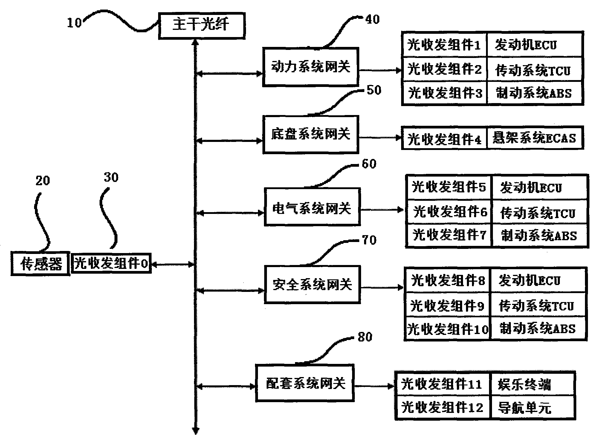
[0020] as attached figure 1 As shown, the automotive electrical system based on optical fiber network described in this embodiment adopts a bus structure, with a single backbone optical fiber as the backbone network, all sensors are shared through the backbone network, and each ECU is connected to the backbone network through a gateway. The system framework of the optical fiber network described in the present invention draws lessons from the design concept of GMLAN, a general company of the United States, and uses the specified architecture (OSI) for open system interconnection as a model to establish a high-speed and effective communication framework. According to the characteristics of automotive communication, the physical layer, data link layer, network layer, transport layer, and application layer are mainly introduced; the automotive electrical system based on optical fiber network developed based on this model can fully meet the needs of vehicle electrical systems now a...


PUM


Abstract

The invention relates to an optical network-based automobile electric system. The optical network-based automobile electric system comprises a main optical fiber, a sensor, an optical receiving and transmitting assembly, a gateway and a peripheral assembly of an automobile, wherein an electric signal measured by the sensor can be converted into an optical signal through the optical receiving and transmitting assembly and can be transmitted to the peripheral assembly of the automobile through a main network, the gateway and the optical receiving and transmitting assembly; the peripheral assembly of the automobile comprises an engine ECU (Electronic Control Unit), a transmission system TCU (Transmission Control Unit), a brake system ABS (Anti-lock Brake System), a light control ECU, a door and window control ECU, a power distribution ECU, an antitheft ECU, an SRS (Supplementary Restraint System) ECU, a back-up ECU, an entertainment terminal and a navigation unit. According to the optical network-based automobile electric system disclosed by the invention, an optical control signal can be transmitted through the main optical fiber, not only can the problems of electric short circuit, electromagnetic disturbance and degraded and melt-down circuit be completely avoided by a control circuit, but also various communication protocols including CAN (Controller Area Network), LIN (Local Interconnect Network), FlexRay and MOST (Media Oriented System Transport) can be simultaneously compatible, a video signal can be quickly transmitted, and the requirements on high speed and sharing of information of the automobile can be met.

Description

technical field [0001] The invention belongs to the technical field of automotive electrical control systems, and more specifically, the invention relates to an automotive electrical system based on an optical fiber network. Background technique [0002] Traditional automotive electrical control systems use electrical wires made of metal such as copper as the conduction and connection of control signals. For example, in a car with a central control computer, in order to precisely control various peripheral components of the car, such as engine, transmission system, braking system, suspension, door frame, power distribution, anti-theft, airbag, reversing, entertainment and navigation, etc., it is necessary to A large number of electrical wires made of metal are connected to the central control computer and the drive lines of peripheral components to transmit various electrical control signals so that each peripheral component can work normally. [0003] However, with the rap...

Claims


Application Information

Patent Timeline
Patent Type & Authority Applications(China)
IPC IPC(8): B60R16/023
Inventor 姚纪荣
Owner JIANGSU TONGMING GAOKE AUTOMOTIVE ELECTRICAL EQUIP
Why Eureka
Try Eureka