
Data center network system and data communication method based on software definition

A data center network and software-defined technology, applied in the direction of data exchange network, digital transmission system, transmission system, etc., can solve the problems of network time extension, bandwidth and performance bottlenecks, poor scalability, etc., to reduce management and operation complexity, Low cost of network structure, effect of reducing manpower and financial resources

Active Publication Date: 2013-12-11
CHONGQING UNIV
View PDF2 Cites 38 Cited by
  • Summary
  • Abstract
  • Description
  • Claims
  • Application Information

AI Technical Summary

Problems solved by technology

The Fat-tree structure improves network reliability to a certain extent, but there are many design defects: 1) Poor scalability, as the number of switches increases, the internal wiring of the network is particularly complicated
2) Core switch bottleneck, the core switch is the bottleneck of bandwidth and performance
3) Excessive energy consumption, energy consumption is one of the key issues that data center operators cannot ignore
However, the Helios structure also has some shortcomings: 1) The delay is large, and the optical circuit switch is used in optical switching, that is, the switch based on the micro-electromechanical system (MEMS). When the traffic matrix changes, the reconstruction process of the optical circuit switch is very time-consuming , usually tens of milliseconds, resulting in a relatively long network delay
2) High energy consumption
The OSA network structure can realize coarse-grained flexible bandwidth and improve network throughput, but there are also shortcomings: 1) The delay is large. This structure uses MEMS switches for signal exchange, and its reconstruction time generally takes tens of milliseconds, so this structure cannot cope Applications with rapid traffic fluctuations
2) It is not easy to handle burst traffic. Compared with packet switching, optical circuit switching does not support burst traffic well.
[0006] To sum up, the existing data center network structure is difficult to meet the bandwidth, delay and energy consumption requirements of future cloud computing data processing and transmission, which has become the bottleneck of modern cloud computing data centers

Method used


Image

  • Data center network system and data communication method based on software definition
  • Data center network system and data communication method based on software definition
  • Data center network system and data communication method based on software definition

Examples


Embodiment 1

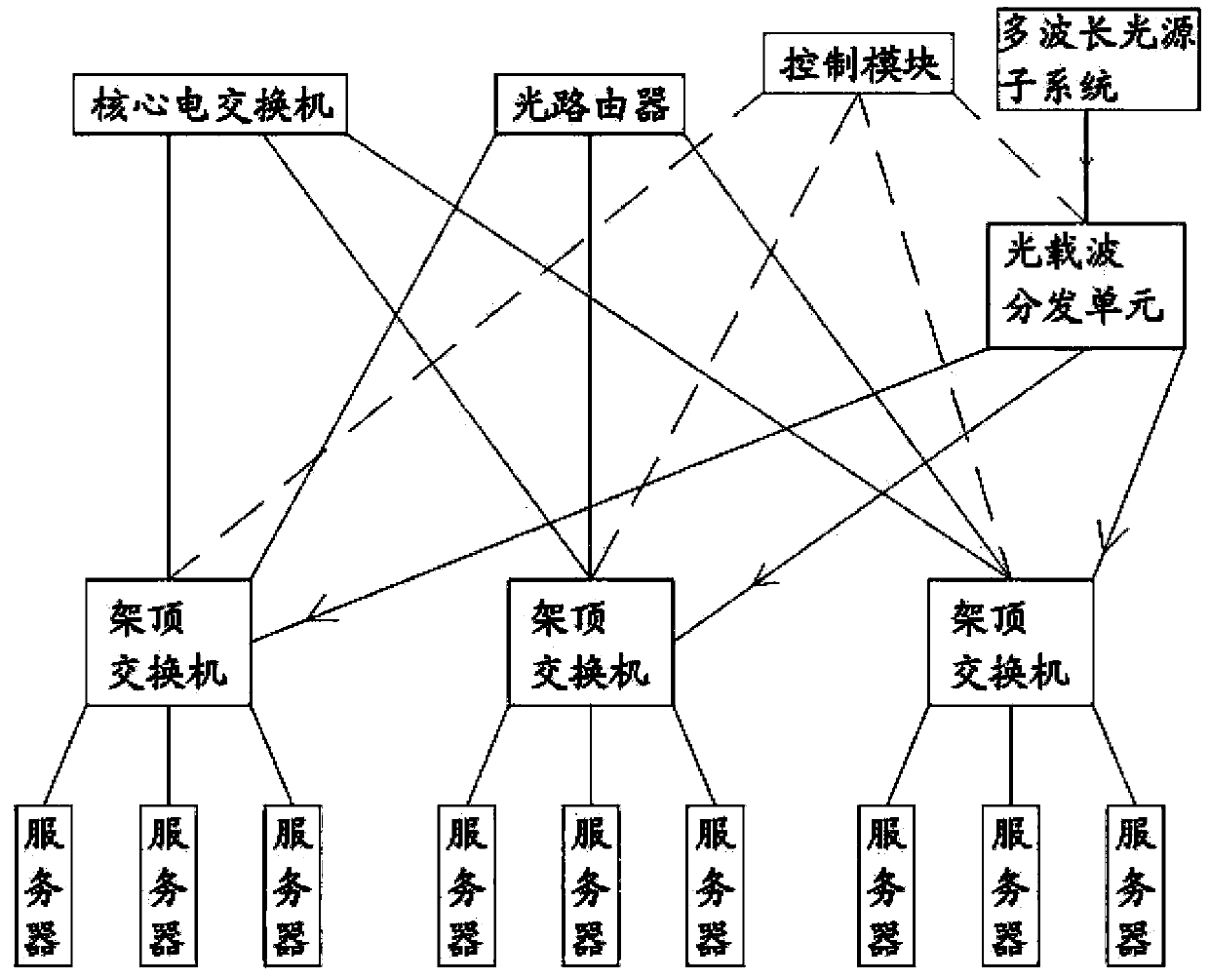
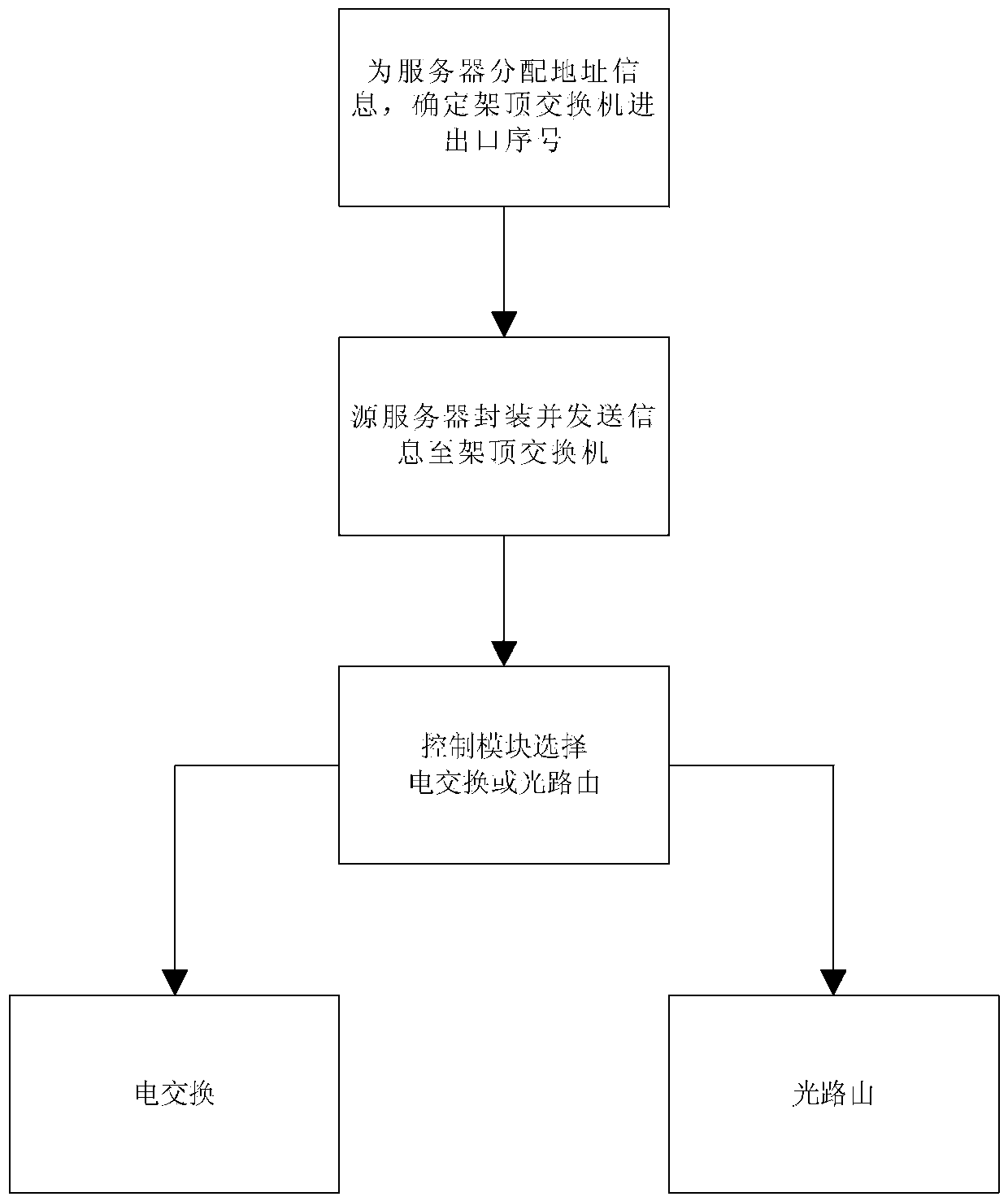
[0052] like Image 6 As shown, the data packet reaches the top-of-rack switch through the copper cable, and after being analyzed by the control module, the data is transmitted through the electrical switching network. Server A sends a connection request to server B, and first sends the data packet to the top-of-rack switch for buffering. The control module decides to transmit the data packet through the electrical switching network according to the data analyzing the traffic characteristics and the buffer information of the switch.

[0053] Data packets buffered at the top-of-rack switch are modulated onto an optical carrier, and then reach the core electrical switch through optical fibers.

[0054] The photoelectric conversion is performed at the port of the core electrical switch, which is converted into an electrical signal for storage and matched with the address of the output port. After the electro-optical conversion, it is forwarded through the output port, and then tr...

Embodiment 2

[0057] like Figure 7 As shown, the data packet reaches the top-of-rack switch through the copper cable, is analyzed by the control module, and transmits the data through the optical routing network. Server C sends a connection request to server D, and first sends the data packet to the top-of-rack switch for buffering, and the control module determines the data packet to transmit data through the optical routing network based on the analysis of the traffic characteristics and the data of the buffer information of the switch.

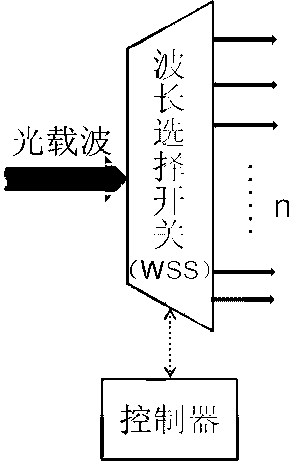
[0058] The top-of-rack switch aggregates the data information, modulates the data information of the electrical signal to the optical carrier signal of a specific wavelength, forwards it to the output port, and transmits it to the C-AWGR through the optical fiber. The top-of-rack switch aggregates the data information to the same destination top-of-rack switch, modulates it to the optical carrier signal of a specific optical wavelength under the coordin...


PUM


Abstract

The invention provides a data center network system and data communication method based on software definition and relates to the technical field of cloud calculating data centers. The data center network system structurally comprises a core electric switch, an optical router, a top-of-rack switch, servers, a control module, an optical carrier wave distribution unit and a multi-wavelength light source subsystem. In data communication, communication optical carrier waves are allocated according to the address of the destination server of data and the traffic of the data; the data are sent to the top-of-rack switch after being packaged by the source server; the control module determines and selects an electric switching path or an optical routing path to forward the data according to the address of the destination server and the traffic characteristics of the data information and the corresponding routing algorithm. The top-of-rack switch performs light modulation on the data according to instructions of the control module and forwards the data to the corresponding electric switching or optical routing path. The data center network system and data communication method based on software definition have very good energy saving effect, are low in construction cost and improve the management efficiency of a data center network and the performance of the network.

Description

technical field [0001] The invention relates to the technical field of cloud computing data centers, in particular to a data center network system and a data communication method. Background technique [0002] Cloud computing is a computing model that uses the Internet to access shared resource pools anytime, anywhere, on-demand, and conveniently. Such resource pools include servers, network resources, storage resources, and applications. The data center is the core platform and infrastructure of cloud computing, and the data center network (DCN) is a network that interconnects large-scale servers in the data center to realize large-scale distributed computing, and realizes the transmission and communication of massive data between servers in the data center. There are currently a variety of data center network structures, typical representative structures are Fat-tree (improved electrical switching data center network), Helios (hybrid optical circuit switching and electrica...

Claims


Application Information

Patent Timeline
IPC IPC(8): H04L12/801H04L29/08H04Q11/00
Inventor 蔡岳平晏尧周丽
Owner CHONGQING UNIV
Learn More