Integrated millimeter wave active phased-array antenna

A phased array antenna, millimeter wave technology, applied in antennas, antenna arrays, modular arrays, etc., can solve the problems of small single-channel output power, the number of chips and high and low frequency interconnection lines, and the lack of determination, to improve reliability. The effect of low cost design, chip count reduction, and design cost reduction

Active Publication Date: 2013-12-18
10TH RES INST OF CETC
View PDF2 Cites 70 Cited by
  • Summary
  • Abstract
  • Description
  • Claims
  • Application Information

AI Technical Summary

Problems solved by technology

The disadvantage of this solution is that each channel of the TR component uses a phase shifter alone, resulting in a large number of chips and high and low frequency interconnection lines, which cannot achieve low-cost and reliable design
Its disadvantage is that the tile-type active phased array antenna does not consider thermal design, and the designed single-channel output power is small, which is not suitable for millimeter-wave active phased array antenna design with single-channel output power greater than 50mw
The structural load-bearing function is not considered in the design of the antenna structure, and a millimeter-wave active phased array antenna that is highly integrated with the system platform structure and directly bears environmental loads cannot be formed
[0007] In general, the traditional millimeter-wave active phased array antenna does not integrate the antenna bearing layer, antenna array, ...

Method used


Image

  • Integrated millimeter wave active phased-array antenna
  • Integrated millimeter wave active phased-array antenna
  • Integrated millimeter wave active phased-array antenna

Examples


Embodiment Construction

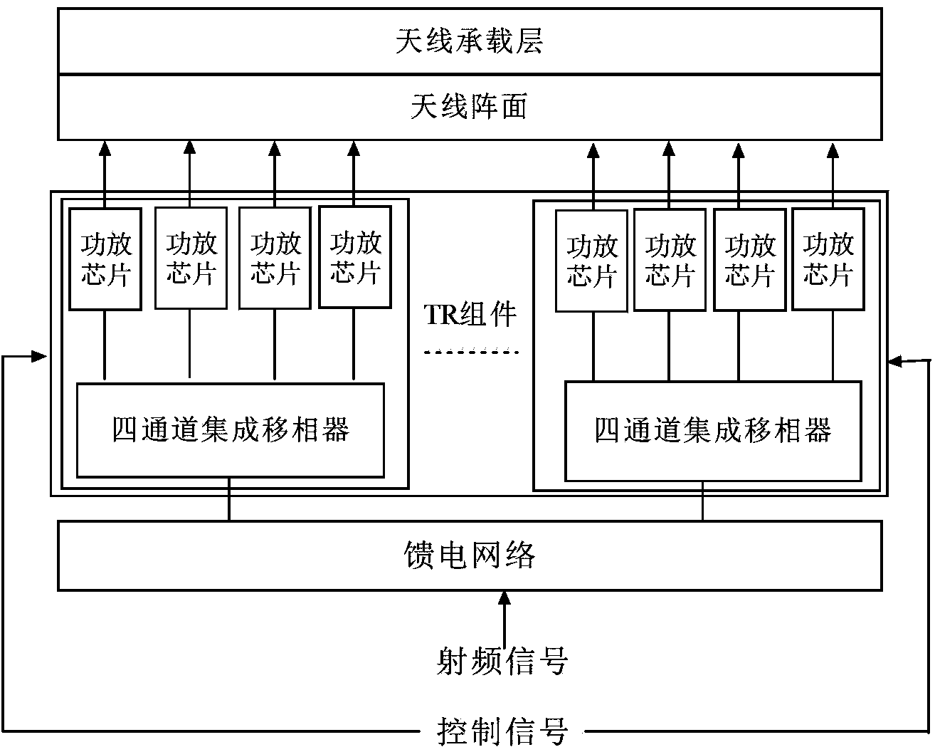
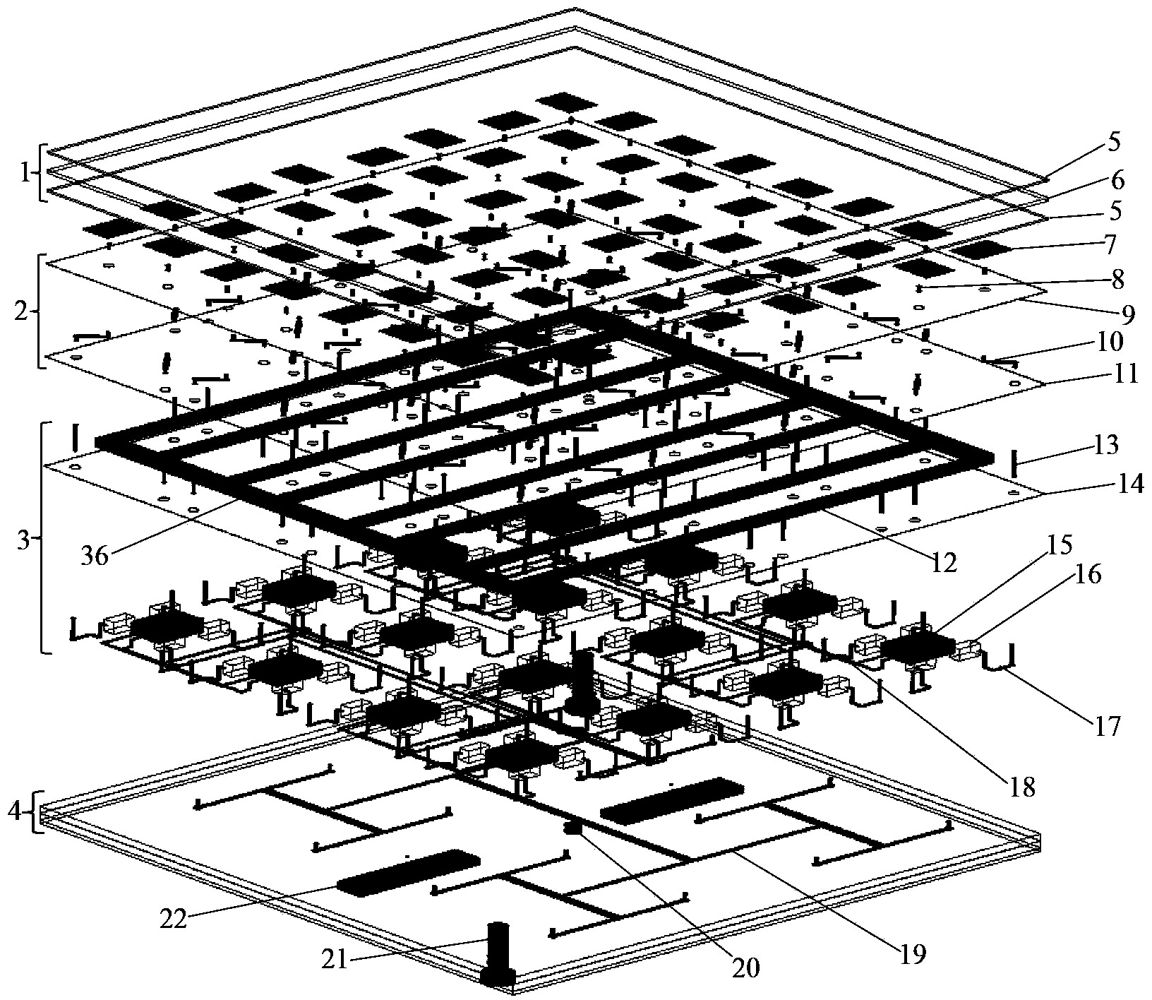
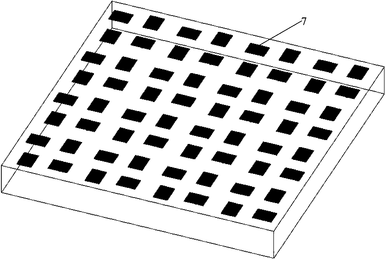
[0029] refer to Figure 1-Figure 4 . In the embodiments described below, taking the integrated millimeter-wave active phased array antenna working at 31 GHz as an example, the array size is taken as 8×8. The millimeter-wave active phased array antenna mainly includes an antenna array 2 integrally connected with the antenna bearing layer 1 , a TR component 3 , and a feed network 4 connected to the TR component 3 . The antenna front 2 uses the microstrip patch 7 as the radiating unit, takes 0.52 wavelengths of the working frequency as the unit spacing, and lays out the rectangular grid array under the antenna bearing layer 1, and the radiating units are connected in an 8×8 array scale to the TR component 3 power amplifier chip 16, and each power amplifier chip 16 of the TR assembly is provided with a heat-conducting metal post 32 that directly guides the heat into the micro-channel 12, and the heat dissipation is connected to the liquid main flow pipe 36 through the liquid cool...


PUM


Abstract

The invention provides an integrated millimeter wave active phased-array antenna. The integrated millimeter wave active phased-array antenna is reliable in performance, ensures that the number of chips can be reduced, and reduces cost. According to the technical scheme, an antenna bearing layer is integrally connected to a feed network through an antenna array surface and a TR assembly; micro-strip patches of the antenna array surface are arranged below the antenna bearing layer according to a rectangular grid array and are connected with power amplifier chips of the TR assembly according to a 8*8 array scale, and every four power amplifier chips are connected with a four-channel integrated phase shifter to constitute a 2*2 sub-array circuit to be integrally connected with the feed network downwards; a radio frequency signal is input to a power dividing network through the feed network and is disseminated into four paths of radio frequency signals through a plurality of four-channel integrated phase shifters, and the radio frequency signals are input into corresponding power amplifier chips, are transmitted to the micro-strip patches and are transmitted; sixteen four-channel integrated phase shifters and sixty-four power amplifier chips are controlled by control signals through a low-frequency signal network to finish radio frequency signal space power synthesis and beam scanning.

Description

technical field [0001] The invention relates to an array antenna and millimeter wave active phased array antenna technology. Background technique [0002] In recent years, with the rapid development of mobile communication services, the rapid progress of millimeter-wave monolithic integrated circuits and high-speed digital processing chips has made the application of high-density integrated millimeter-wave active phased array antennas possible. With the wide application of my country's on-orbit satellite systems and communication data links, airborne, missile-borne, rocket-borne and other platforms have higher and higher requirements for the transmission rate and installation space of phased array antennas, and phased array antennas are required to have high gain, volume Requirements such as small size, light weight, flexible beam scanning, and wide coverage make the application of millimeter-wave active phased array antennas very urgent. [0003] The high development of mil...

Claims


Application Information

Patent Timeline
IPC IPC(8): H01Q1/12H01Q1/38H01Q3/30
CPCH01Q1/02H01Q21/0025H01Q21/065
Inventor 何庆强何海丹赵青
Owner 10TH RES INST OF CETC
Why Eureka
Try Eureka