Stress testing device for non-metal anti-floating anchor rod body

An anti-floating anchor rod and stress testing technology, which is applied in the measurement of the change force of the optical properties of the material when it is stressed, can solve the problems of easy falling off of the strain gauge, low spatial resolution, missing data, etc., and achieve anti- Strong electromagnetic field interference ability, high measurement accuracy and convenient installation

Inactive Publication Date: 2013-12-25
QINGDAO TECHNOLOGICAL UNIVERSITY
View PDF7 Cites 24 Cited by
  • Summary
  • Abstract
  • Description
  • Claims
  • Application Information

AI Technical Summary

Problems solved by technology

The surface of the GFRP spiral rib is uneven, and there are some problems in the existing stress test equipment for the anchor rod body. When the strain gauge is pasted or the surface of the rod body is implanted with optical fibers, grinding will cause the surface fiber to be broken, resulting in the initial defect of the anchor rod, and the strain gauge is easy to Therefore, it is not reasonable to use ordinary electrical measurement methods to comprehensively monitor the working properties of GFRP bolts. Optical fibers can be used to test them. Optical fiber testing mainly includes distributed (Brillouin method) and quasi- Distributed (Bragg grating method) two methods, distributed (Brillouin method) uses an optical fiber for continuous testing, suitable for long-distance measurement; quasi-distributed (Bragg grating method) uses a bare optical fiber to connect a string of grating sensors to the anchor rod carry out testing
At present, most of the fiber optic testing of GFRP anchor rods adopts distributed (Brillouin method). This method can test continuously in name, but the spatial resolution is low, and the accuracy of measuring point positioning can only reach 20cm at most, which is not suitable for fighting against floating anchor rods. Short components are tested, especially the stress concentration change area near the orifice cannot be accurately located

Method used


Image

  • Stress testing device for non-metal anti-floating anchor rod body
  • Stress testing device for non-metal anti-floating anchor rod body
  • Stress testing device for non-metal anti-floating anchor rod body

Examples


Embodiment

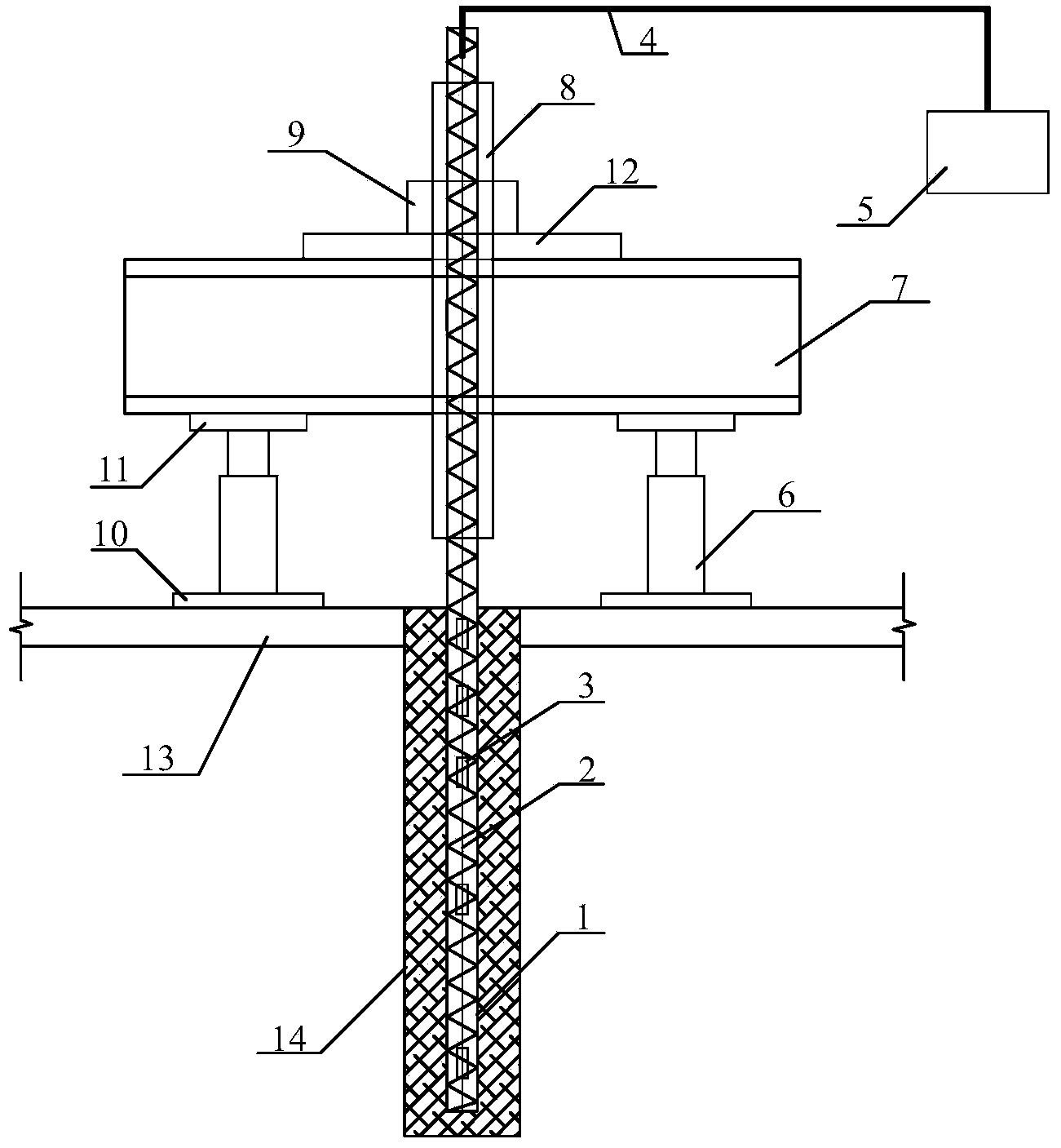
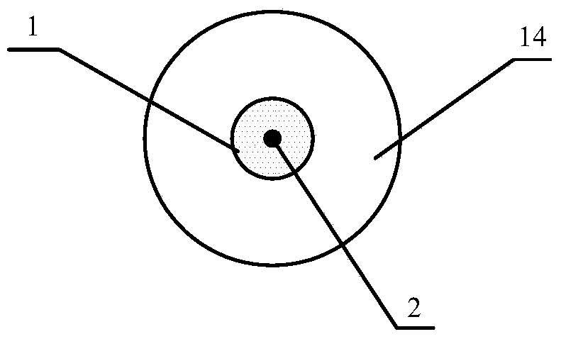
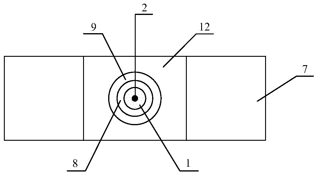
[0021] The main structure of this embodiment includes an anchor rod body 1, a bare optical fiber 2, a grating sensor 3, an armored optical cable 4, a data acquisition system 5, a jack 6, a reaction beam 7, a steel sleeve 8, an anchor 9, and a first steel plate 10. The second steel plate 11, the third steel plate 12, the cushion layer 13 and the anchor hole 14; the lower end of the glass fiber reinforced polymer (GFRP) fully threaded solid structure anchor body 1 is inserted into the anchor hole 14; the bare optical fiber 2 The grating sensor 3 is engraved to form a bare fiber grating string, and the middle part of the anchor rod 1 is buried with a fiber grating string along the length direction. The outer surface coating of the bare optical fiber 2 is a polymer that has fusion properties with the anchor rod body 1; The bare optical fiber 2 at the end of the rod body 1 is protected by an armored optical cable 4, and the armored optical cable 4 is connected to the data acquisitio...


PUM


Abstract

The invention belongs to the technical field of stress testing devices and relates to a stress testing device for a non-metal anti-floating anchor rod body. The stress testing device is characterized in that the lower end of an anchor rod body is inserted into an anchor rod hole; a grating sensor is etched into a bare fiber to form a fiber grating string, and the fiber grating string is buried and strung into the middle of an anchor rod; an armored cable for protecting the bare fiber at the tip of the anchor rod body is connected with a data collection system; two first steel plates are mounted on the upper surface of a cushion layer and are placed on two sides of the anchor rod body, and lifting jacks are placed at the middles of the first steel plates; counter-force beams in which holes are preformed in the middles are placed on the lifting jacks, and second steel plates are additionally arranged between the counter-force beams and the lifting jacks; a third steel plate is arranged on the tops of the counter-force beams, and an anchoring tool is fixedly arranged on the third steel plate; a steel sleeve is sleeved on the upper end of the anchor rod body, the inner side of the steel sleeve is connected with the anchor rod body, and the outer side of the steel sleeve is connected with the anchoring tool. The stress testing device is simple in structure, high in measurement accuracy, sensitivity and survival rate and strong in electromagnetic field interference resistance, is convenient to mount and is capable of realizing automatic monitoring.

Description

Technical field: [0001] The invention belongs to the technical field of stress testing equipment, and relates to a stress testing device for a non-metallic bolt body in geotechnical engineering, in particular to a stress testing device for a non-metallic anti-floating bolt body. Background technique: [0002] With the development and utilization of urban underground space, the buried depth of the foundation of buildings (structures) increases continuously, and the problem of anti-floating becomes more and more prominent. , anti-floating bolts have strong stratum adaptability, flexible layout, fast hole formation, small construction site, miniaturized construction machinery, economical and environmental protection, large bearing capacity in hard rock and soil layers, glass fiber reinforced polymer (GFRP) The emergence of bolts has added new means to rock and soil anchoring, especially the excellent corrosion resistance and anti-electromagnetic interference characteristics of ...

Claims


Application Information

Patent Timeline
Patent Type & Authority Applications(China)
IPC IPC(8): G01L1/24
Inventor 张明义白晓宇张鹏闫楠寇海磊
Owner QINGDAO TECHNOLOGICAL UNIVERSITY
Why Eureka
Try Eureka