Phased-array antenna based on dynamic-regulating artificial electromagnetic structural materials

A phased array antenna, artificial electromagnetic technology, applied in the direction of antennas, circuits, electrical components, etc., can solve the problems of large insertion loss, and achieve the effect of low insertion loss, low cost, and large continuous beam scanning angle width

Active Publication Date: 2013-12-25
INST OF OPTICS & ELECTRONICS - CHINESE ACAD OF SCI
View PDF4 Cites 54 Cited by
  • Summary
  • Abstract
  • Description
  • Claims
  • Application Information

AI Technical Summary

Problems solved by technology

However, the above-mentioned dynamic adjustment and control of beam scanning artificial electromagnetic structure materials have a common problem, the insertion loss is large, and only one-dimensional dynamic scanning can be realized.

Method used


Image

  • Phased-array antenna based on dynamic-regulating artificial electromagnetic structural materials
  • Phased-array antenna based on dynamic-regulating artificial electromagnetic structural materials
  • Phased-array antenna based on dynamic-regulating artificial electromagnetic structural materials

Examples


Embodiment 1

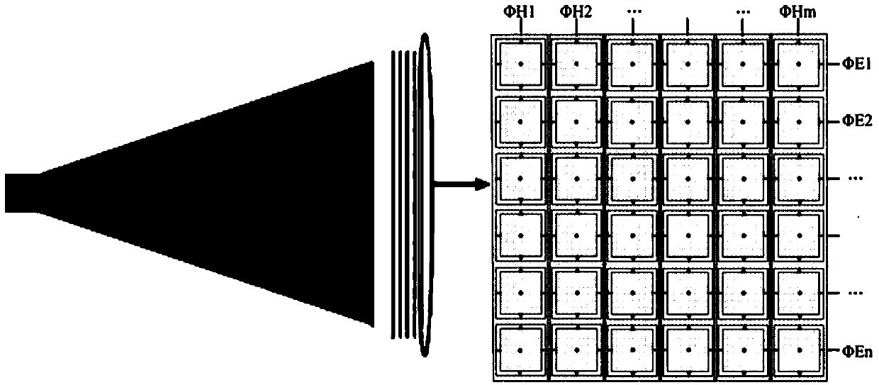
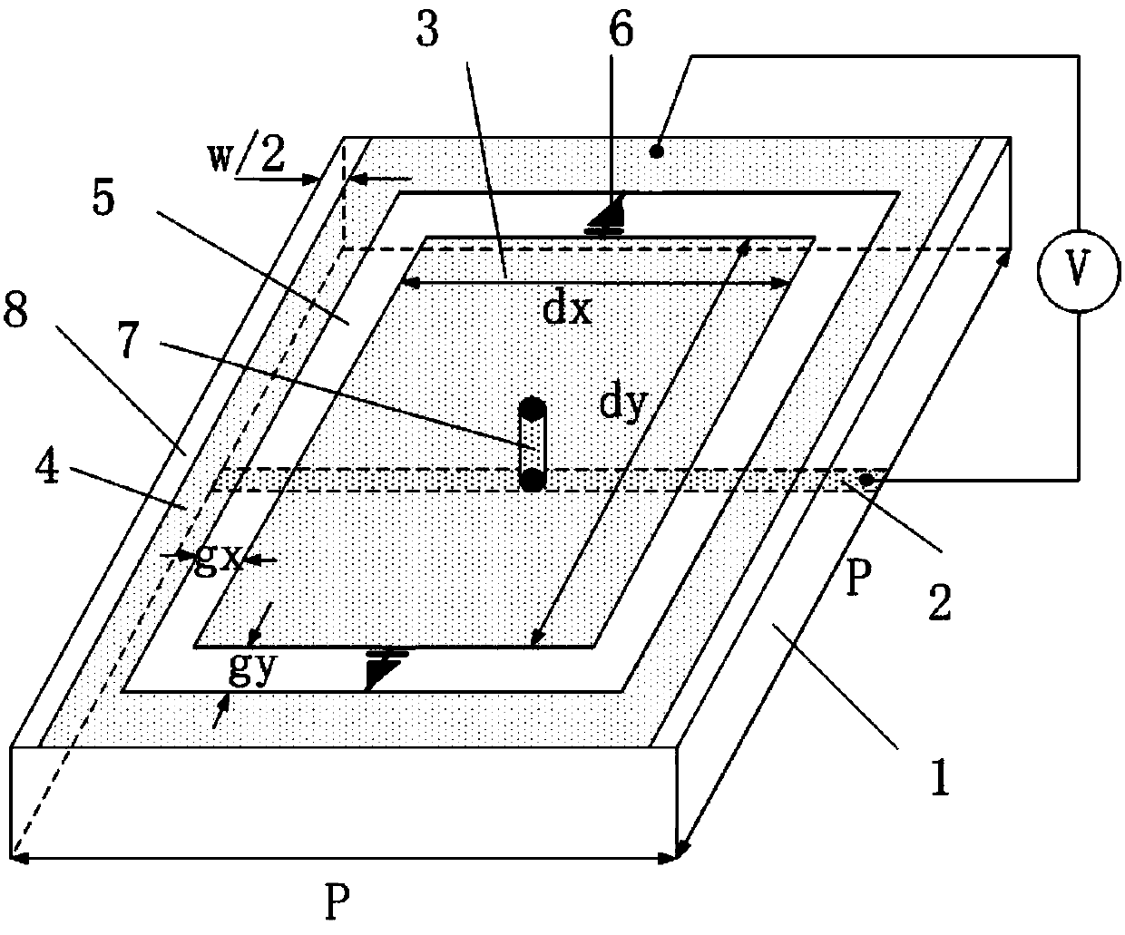
[0040] In this embodiment, an overall model of a scanning antenna based on a five-layer (6×6) unit period for dynamic control of artificial electromagnetic structural materials is designed for a frequency of 5 GHz. The horn antenna is used as the feed source, the radiation aperture is 183mm×206mm, the distance between the horn mouth and the material is 18.5mm, and the layer spacing h=6.5mm of the artificial electromagnetic structure material is dynamically adjusted. The dielectric substrate of the dynamically regulated artificial electromagnetic structure material adopts 1.5mm thick TLX-8 (ε=2.55, loss tangent is 0.0027), and the metal rectangular patch is connected with metal leads through metallized holes with a diameter of 0.15mm. The structural dimensions of other sub-wavelength units are: p=33mm, dx=24.5mm, dy=23.5mm, gx=3.25mm, gy=3.05mm, w=0.4mm, d=0.2mm.

[0041] First, we use electromagnetic simulation software to simulate the sub-wavelength unit structure. The direct...

Embodiment 2

[0049] Based on the above, this embodiment conducts experimental measurements on the special cases of four deflection angles (0°, 10°, 20° and 30°) in E-plane beam scanning. When ΦHm is connected to the same low potential and ΦEn is controlled by six independent high potentials, the material can be divided into six regions in the direction of electric field polarization. Control the phase difference. The radiation pattern of the antenna in the E plane is measured under four different situations. We connect all ΦHn to 30V high potential. Table 2 gives the potential ΦEm of each region corresponding to the four deflection states. Test results such as Figure 9 with Figure 10 as shown, Figure 9 It is the return loss S11 of the antenna corresponding to the four deflection angles, and the return loss of the antenna at the working frequency is less than -10dB; Figure 10 It shows the far-field radiation patterns corresponding to the four cases at 5.3GHz, and the measured defl...

Embodiment 3

[0053] In this embodiment, experimental measurements are made for the special cases of four deflection angles (0°, 10°, 20° and 30°) in H-plane beam scanning. When Φ Em ground, Φ Hn When controlled by six independent high potentials, the material can be divided into six regions in the direction of magnetic field polarization. The radiation pattern of the antenna in four different cases is simulated respectively. In the first case, all the voltages in the six regions are set to be the same (10V), so that the transmission phases of each region are equal. In the second case, set appropriate capacitance values ​​in different regions, and ensure that the transmission phase increases sequentially along the x-axis direction. The difference between adjacent regions is 36°. In the third case, the phase difference between adjacent regions is 70°. The four cases are 103°, and Table 3 shows the distribution of specific voltage values. Test results such as Figure 11 with Figure 12 ...


PUM


Abstract

The invention provides a phased-array antenna based on dynamic-regulating artificial electromagnetic structural materials. The phased-array antenna comprises a horn feed source and multiple layers of the dynamic-regulating artificial electromagnetic structural materials covering the upper portion of the horn feed source. Each layer of the materials is formed in the modes that metal patches with annular gaps distributed periodically are printed on the front of a dielectric slab, variable capacitance diodes are embedded in vertical centers of the annular gaps, gap lines used for isolating direct currents are etched between the annular gaps in different columns, and metal leads are printed on the back of the dielectric slab and via holes are metallized so that direct-current voltage can be provided for the metal patches in the annular gaps in different rows. Capacitance of the variable capacitance diodes between different rows or different columns is adjusted through controlling of a direct-current voltage source, so that radiation phases of regions in adjacent rows or adjacent columns gradually increase or decrease, the phase different value is dynamically adjusted, and dynamic scanning of antenna beams can be achieved. The phased-array antenna has the advantages of being simple in structure, convenient to power up, low in insertion loss, low in cost and the like and can achieve two-dimensional dynamic scanning of an E face and an H face.

Description

technical field [0001] The invention relates to the field of phased array antennas, in particular to a phased array antenna based on dynamic control of artificial electromagnetic structural materials. Background technique [0002] The phased array antenna has the characteristics of steerable beam direction, and has been widely used in the field of tracking one or more targets. But the phased array antenna is expensive and the feed network is complicated. Therefore, many researchers have been focusing on finding a simple method to realize antenna beam scanning, such as using easy-to-manipulate, low-loss phased array materials to realize beam scanning. [0003] For a long time, periodic artificial electromagnetic structural materials with adjustable electromagnetic properties have attracted the attention of more and more researchers. Due to their unique properties, such as tunable dielectric constant and refractive index, artificial electromagnetic structural materials have ...

Claims


Application Information

Patent Timeline
Patent Type & Authority Applications(China)
IPC IPC(8): H01Q3/34H01Q13/02H01Q15/00
Inventor 罗先刚黄成马晓亮王长涛蒲明博潘文波崔建华赵波
Owner INST OF OPTICS & ELECTRONICS - CHINESE ACAD OF SCI
Why Eureka
Try Eureka