Phased-array antenna based on dynamic-regulating artificial electromagnetic structural materials
A phased array antenna and artificial electromagnetic technology, which is applied to antennas, circuits, electrical components, etc., can solve the problems of large insertion loss and achieve the effects of low insertion loss, convenient power-on, and simple structure
- Summary
- Abstract
- Description
- Claims
- Application Information
AI Technical Summary
Problems solved by technology
Method used
Image
Examples
Embodiment 1
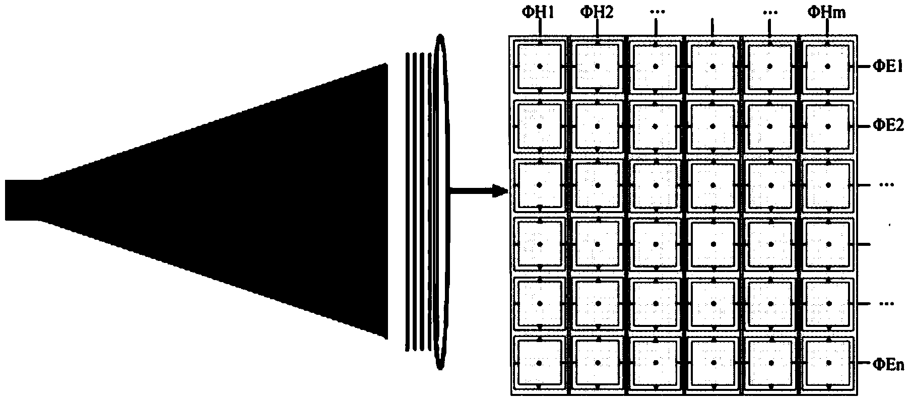
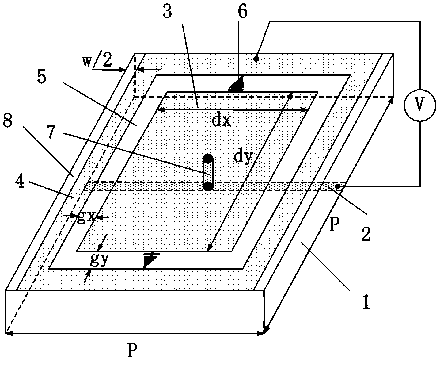
[0040] In this embodiment, an overall model of a scanning antenna based on a five-layer (6×6) unit period for dynamic control of artificial electromagnetic structural materials is designed for a frequency of 5 GHz. The horn antenna is used as the feed source, the radiation aperture is 183mm×206mm, the distance between the horn mouth and the material is 18.5mm, and the layer spacing h=6.5mm of the artificial electromagnetic structure material is dynamically adjusted. The dielectric substrate of the dynamically regulated artificial electromagnetic structure material adopts 1.5mm thick TLX-8 (ε=2.55, loss tangent is 0.0027), and the metal rectangular patch is connected with metal leads through metallized holes with a diameter of 0.15mm. The structural dimensions of other sub-wavelength units are: p=33mm, dx=24.5mm, dy=23.5mm, gx=3.25mm, gy=3.05mm, w=0.4mm, d=0.2mm.
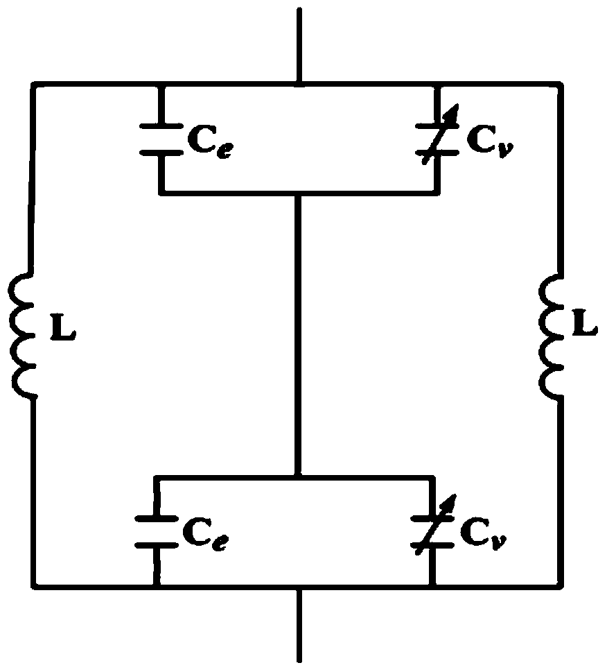
[0041] First, we use electromagnetic simulation software to simulate the sub-wavelength unit structure. The direct...
Embodiment 2
[0049] Based on the above, this embodiment conducts experimental measurements on the special cases of four deflection angles (0°, 10°, 20° and 30°) in E-plane beam scanning. When ΦHm is connected to the same low potential and ΦEn is controlled by six independent high potentials, the material can be divided into six regions in the direction of electric field polarization. Control the phase difference. The radiation pattern of the antenna in the E plane is measured under four different situations. We connect all ΦHn to 30V high potential. Table 2 gives the potential ΦEm of each region corresponding to the four deflection states. Test results such as Figure 9 with Figure 10 as shown, Figure 9 It is the return loss S11 of the antenna corresponding to the four deflection angles, and the return loss of the antenna at the working frequency is less than -10dB; Figure 10 It shows the far-field radiation patterns corresponding to the four cases at 5.3GHz, and the measured defl...
Embodiment 3
[0053] In this embodiment, experimental measurements are made for the special cases of four deflection angles (0°, 10°, 20° and 30°) in H-plane beam scanning. When Φ Em ground, Φ Hn When controlled by six independent high potentials, the material can be divided into six regions in the direction of magnetic field polarization. The radiation pattern of the antenna in four different cases is simulated respectively. In the first case, all the voltages in the six regions are set to be the same (10V), so that the transmission phases of each region are equal. In the second case, set appropriate capacitance values in different regions, and ensure that the transmission phase increases sequentially along the x-axis direction. The difference between adjacent regions is 36°. In the third case, the phase difference between adjacent regions is 70°. The four cases are 103°, and Table 3 shows the distribution of specific voltage values. Test results such as Figure 11 with Figure 12 ...
PUM
 Abstract
Description
Claims
Application Information
 - R&D
- Intellectual Property
- Life Sciences
- Materials
- Tech Scout
- Unparalleled Data Quality
- Higher Quality Content
- 60% Fewer Hallucinations
Browse by: Latest US Patents, China's latest patents, Technical Efficacy Thesaurus, Application Domain, Technology Topic, Popular Technical Reports.
© 2025 PatSnap. All rights reserved.Legal|Privacy policy|Modern Slavery Act Transparency Statement|Sitemap|About US| Contact US: help@patsnap.com


